Low-temperature and low-damage multifunctional composite coating device and method
A composite coating, multi-functional technology, applied in sputtering coating, ion implantation coating, vacuum evaporation coating and other directions, can solve the problems of damage temperature, low thermal conductivity of flexible materials, temperature rise, etc., to achieve low temperature, low damage and high speed The effect of uniform deposition, reduction of thermal and optical radiation, and increased deposition rate
- Summary
- Abstract
- Description
- Claims
- Application Information
AI Technical Summary
Problems solved by technology
Method used
Image
Examples
Embodiment 1
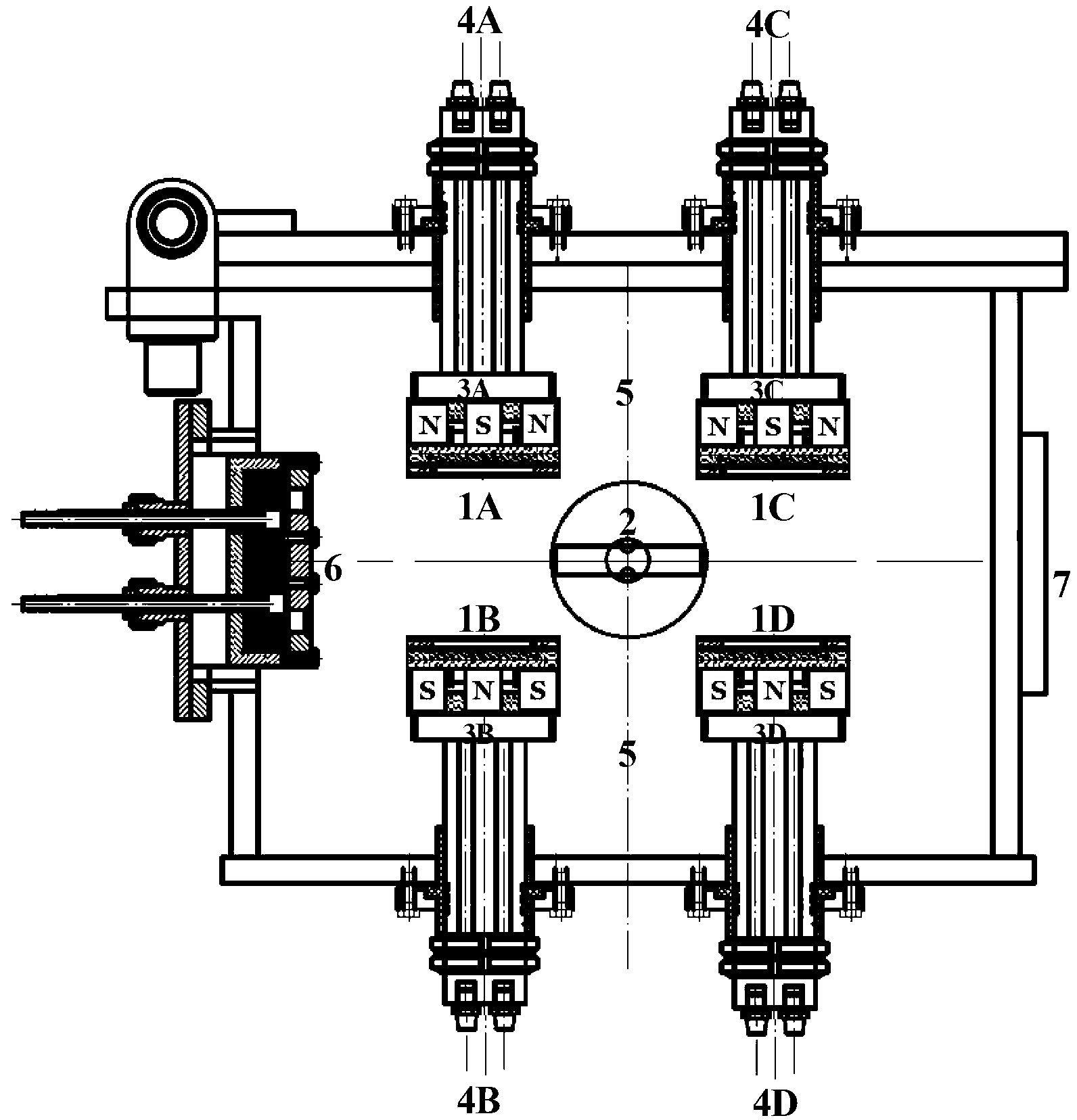
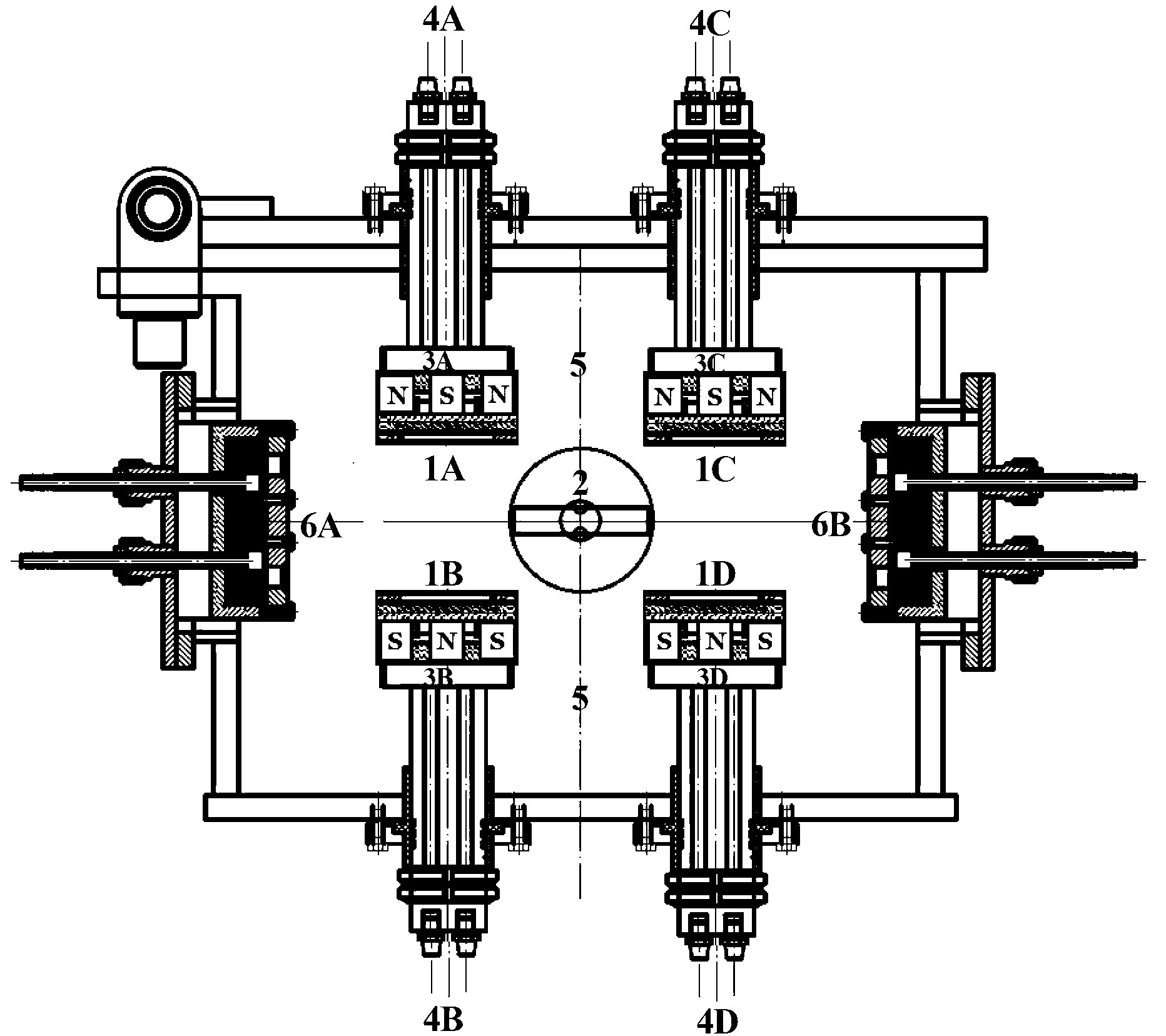
[0042] Such as figure 1 As shown, the whole vacuum system of the device of the present invention mainly includes: the first group of targets (the A side 1A of the first group of targets and the B side 1B of the first group of targets) arranged in the vacuum cavity 5, the workpiece turret 2, Magnet system (magnet system A part 3A, magnet system B part 3B), low temperature linear ion source 6, and the second set of targets (the second set of target C surface 1C and the second set of target D surface 1D), the magnet system (Magnet system C part 3C, magnet system D part 3D), etc. The specific structure is as follows:
[0043] The surface 1A of the first group of target materials and the surface 1B of the first group of target materials are set opposite to each other, with a distance of 12cm, and the angle between the target and the target is 0 degrees. The ion source 6 is located on the side of the first group of targets, and plays the role of ion cleaning and auxiliary depositi...
Embodiment 2
[0051] Such as figure 1 As shown, the whole vacuum system of the device of the present invention mainly includes: the first group of targets (the first group of target A side 1A and the first group of target B side 1B) arranged in the vacuum chamber 5, the workpiece turret 2, Magnet system (magnet system A part 3A, magnet system B part 3B), low temperature linear ion source 6, and the second set of targets (the second set of target C surface 1C and the second set of target D surface 1D), the magnet system (Magnet system C part 3C, magnet system D part 3D), etc. The specific structure is as follows:
[0052] The surface 1A of the first group of target materials and the surface 1B of the first group of target materials are set opposite to each other, with a distance of 12cm, and the angle between the target and the target is 0 degrees. The ion source 6 is located on the side of a group of targets, and plays the role of ion cleaning and auxiliary deposition. The low-temperature...
Embodiment 3
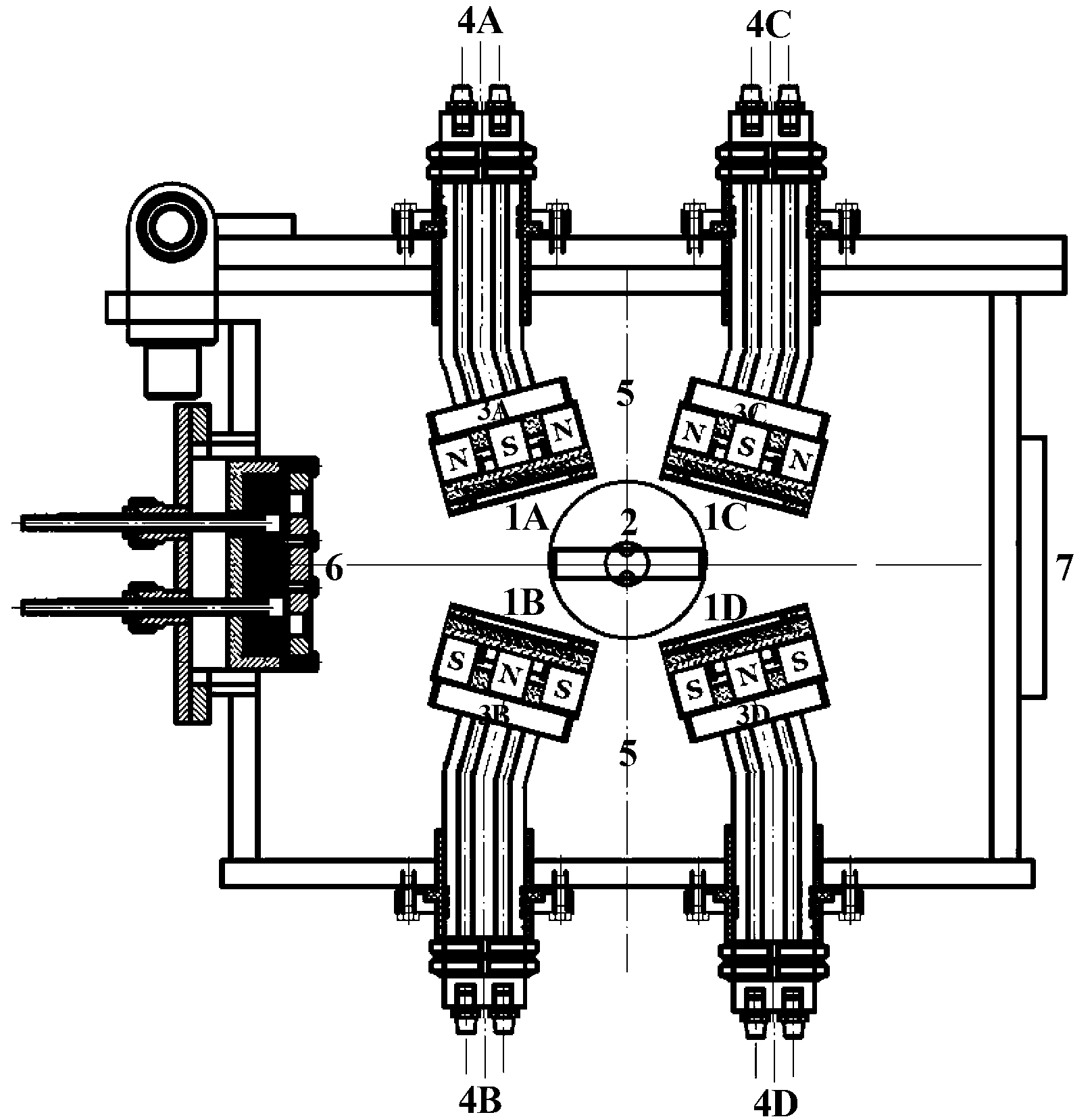
[0060] Such as figure 2As shown, the entire vacuum system of the device of the present invention mainly includes: the first group of targets (the first group of target A side 1A and the first group of target B side 1B) arranged in the vacuum chamber 5, the second group of target (The second group of targets C surface 1C and the second group of targets D surface 1D), workpiece turret 2, magnet system (magnet system A part 3A, magnet system B part 3B), magnet system (magnet system C part 3C, Magnet system D part 3D), low temperature linear ion source 6, etc. The specific structure is as follows:
[0061] The first group of targets A surface 1A and the first group of targets B surface 1B are set opposite to each other, with a distance of 12cm, and the angle between targets is 15 degrees, and the second group of targets C and surface 1C are opposite to the second group of targets D. Set, the distance is 12cm, and the angle between target and target is 15 degrees. The workpiece...
PUM
 Abstract
Description
Claims
Application Information
 - R&D
- Intellectual Property
- Life Sciences
- Materials
- Tech Scout
- Unparalleled Data Quality
- Higher Quality Content
- 60% Fewer Hallucinations
Browse by: Latest US Patents, China's latest patents, Technical Efficacy Thesaurus, Application Domain, Technology Topic, Popular Technical Reports.
© 2025 PatSnap. All rights reserved.Legal|Privacy policy|Modern Slavery Act Transparency Statement|Sitemap|About US| Contact US: help@patsnap.com


