Low-temperature and low-damage multifunctional composite coating device and method

A composite coating and multi-functional technology, which is applied in the field of low-temperature and low-damage multi-functional composite coating devices, can solve the problems of damage temperature, low thermal conductivity of flexible materials, etc. Effects of radiation, avoiding direct bombardment

Inactive Publication Date: 2015-03-25
INST OF METAL RESEARCH - CHINESE ACAD OF SCI
View PDF5 Cites 0 Cited by
  • Summary
  • Abstract
  • Description
  • Claims
  • Application Information

AI Technical Summary

Problems solved by technology

In these transparent organic optoelectronic devices, it is usually necessary to sputter-deposit a transparent conductive oxide thin film material on the organic material layer as the cathode, but in the traditional magnetron sputtering technology, since the target is parallel to the organic material substrate, the plasma is in the target Between the substrate and the organic material substrate, energetic particles with certain energy such as reflective atoms (argon atoms, oxygen atoms), sputtered atoms, secondary electrons and oxygen negative ions directly bombard the organic material substrate, causing damage and temperature rise High; in addition, the thermal radiation and ultraviolet radiation of the plasma will also cause a certain degree of damage and temperature rise
During this deposition process, the damage and temperature rise of organic materials will directly affect the performance and life of transparent organic optoelectronic devices.
At the same time, traditional rigid displays can no longer meet people's needs for display functions. Flexible displays have the characteristics of lightness, thinness, impact resistance, flexibility, and are not limited by occasions and spaces. However, the thermal conductivity of flexible materials is low, and the surface temperature Easy to rise, which limits the large-scale application of flexible devices

Method used


Image

  • Low-temperature and low-damage multifunctional composite coating device and method
  • Low-temperature and low-damage multifunctional composite coating device and method
  • Low-temperature and low-damage multifunctional composite coating device and method

Examples


Embodiment 1

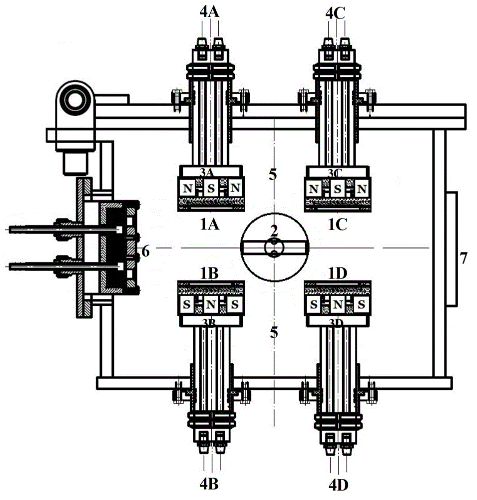
[0042] Such as figure 1 As shown, the whole vacuum system of the device of the present invention mainly includes: the first group of targets (the A side 1A of the first group of targets and the B side 1B of the first group of targets) arranged in the vacuum cavity 5, the workpiece turret 2, Magnet system (magnet system A part 3A, magnet system B part 3B), low temperature linear ion source 6, and the second set of targets (the second set of target C surface 1C and the second set of target D surface 1D), the magnet system (Magnet system C part 3C, magnet system D part 3D), etc. The specific structure is as follows:

[0043] The surface 1A of the first group of target materials and the surface 1B of the first group of target materials are set opposite to each other, with a distance of 12cm, and the angle between the target and the target is 0 degrees. The ion source 6 is located on the side of the first group of targets, and plays the role of ion cleaning and auxiliary depositi...

Embodiment 2

[0051] Such as figure 1 As shown, the whole vacuum system of the device of the present invention mainly includes: the first group of targets (the A side 1A of the first group of targets and the B side 1B of the first group of targets) arranged in the vacuum cavity 5, the workpiece turret 2, Magnet system (magnet system A part 3A, magnet system B part 3B), low temperature linear ion source 6, and the second set of targets (the second set of target C surface 1C and the second set of target D surface 1D), the magnet system (Magnet system C part 3C, magnet system D part 3D), etc. The specific structure is as follows:

[0052] The surface 1A of the first group of target materials and the surface 1B of the first group of target materials are set opposite to each other, with a distance of 12cm, and the angle between the target and the target is 0 degrees. The ion source 6 is located on the side of a group of targets, and plays the role of ion cleaning and auxiliary deposition. The ...

Embodiment 3

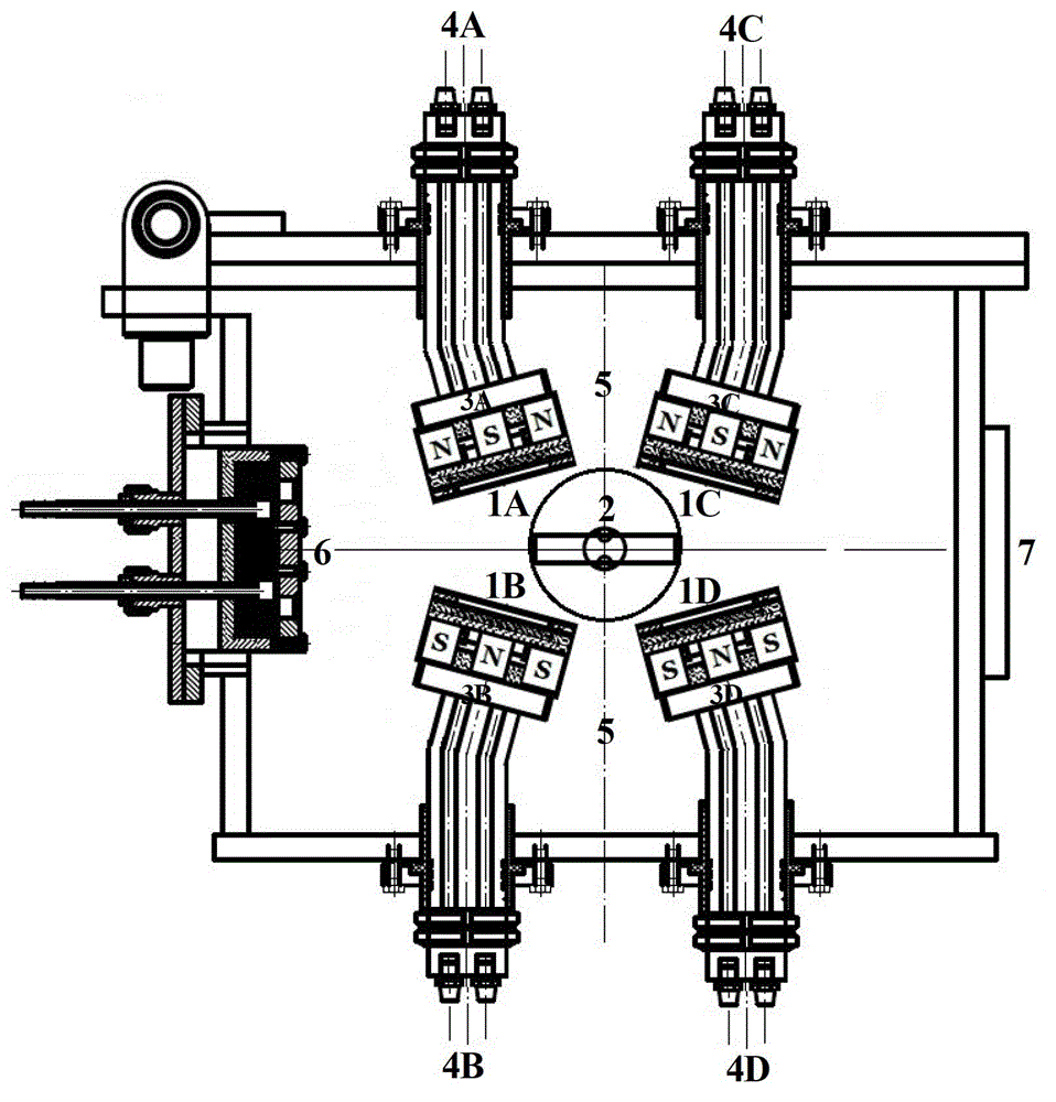
[0060] Such as figure 2As shown, the entire vacuum system of the device of the present invention mainly includes: the first group of targets (the first group of target A side 1A and the first group of target B side 1B) arranged in the vacuum chamber 5, the second group of target (The second group of targets C surface 1C and the second group of targets D surface 1D), workpiece turret 2, magnet system (magnet system A part 3A, magnet system B part 3B), magnet system (magnet system C part 3C, Magnet system D part 3D), low temperature linear ion source 6, etc. The specific structure is as follows:

[0061] The first group of targets A surface 1A and the first group of targets B surface 1B are set opposite to each other, with a distance of 12cm, and the angle between targets is 15 degrees, and the second group of targets C and surface 1C are opposite to the second group of targets D. Set, the distance is 12cm, and the angle between target and target is 15 degrees. The workpiece...


PUM

PropertyMeasurementUnit
thicknessaaaaaaaaaa

Abstract

The invention belongs to the field of film preparation, in particular to a low-temperature and low-damage multifunctional composite coating device and a method. The device comprises a vacuum cavity which comprises two groups of four rectangular nonequilibrium magnetic control targets, an ion source and a workpiece rotating stand. The two groups of nonequilibrium targets are placed side by side; the two targets in each group are placed face to face, and can work independently or simultaneously, distances among the targets are adjustable; angles among the targets are adjustable; the targets are driven by a direct current power supply; and plasma is generated between the targets in each group. The workpiece rotating stand is positioned between the two groups of targets, and the ion source is positioned on the side face of one group of targets for ion cleaning and auxiliary deposition. With the adoption of the device and the method, damages to organic materials such as polymers and temperature rise caused by secondary electrons, oxygen anions and the like can be shielded, and films can be uniformly deposited on the surfaces of the organic materials such as the polymers in a low-temperature, low-damage and high-speed manner through the low-temperature linear ion source auxiliary deposition.

Description

technical field [0001] The invention belongs to the field of thin film preparation, in particular to a low-temperature low-damage multifunctional composite coating device and method. Background technique [0002] Due to the advantages of faster response speed, less energy consumption, higher brightness and manufacturability, transparent organic optoelectronic devices have been used in new flat panel displays, solid-state lighting, flexible displays, high-density information transmission and storage, new energy And photochemical utilization and other fields have shown broad application prospects. In these transparent organic optoelectronic devices, it is usually necessary to sputter-deposit a transparent conductive oxide thin film material on the organic material layer as the cathode, but in the traditional magnetron sputtering technology, since the target is parallel to the organic material substrate, the plasma is in the target Between the substrate and the organic materia...

Claims


Application Information

Patent Timeline
Patent Type & Authority Patents(China)
IPC IPC(8): C23C14/35
Inventor 雷浩肖金泉宫骏孙超
Owner INST OF METAL RESEARCH - CHINESE ACAD OF SCI
Why Eureka
Try Eureka