
Automatic surfacing welding machine and control system for inner and outer walls of wear ring

A technology of automatic surfacing and inner and outer walls, applied in the direction of manufacturing tools, welding rod characteristics, welding equipment, etc., can solve the problems of high technical level requirements for welders, difficulty in welding quality, uneven thickness of surfacing layer, etc., to achieve favorable Labor protection, stable welding quality, and the effects of reducing heat radiation and light radiation

Inactive Publication Date: 2018-11-16
ZHUZHOU ZHENXIANG IND CO LTD
View PDF8 Cites 0 Cited by
  • Summary
  • Abstract
  • Description
  • Claims
  • Application Information

AI Technical Summary

Problems solved by technology

[0002] In the prior art, the surfacing welding of the wear-resistant ring is carried out by manual surfacing operation, which has the following defects: ① the thickness of the surfacing layer is uneven, the size error is large, and the welding quality is difficult to meet the standard; High requirements; ③Welders have high labor intensity and low work efficiency; ④The working environment is poor, and the arc light and smoke generated during welding will cause harm to the welder's body

Method used


Image

  • Automatic surfacing welding machine and control system for inner and outer walls of wear ring
  • Automatic surfacing welding machine and control system for inner and outer walls of wear ring
  • Automatic surfacing welding machine and control system for inner and outer walls of wear ring

Examples


Embodiment Construction

[0018] The specific embodiments of the present invention will be further described below in conjunction with the accompanying drawings.

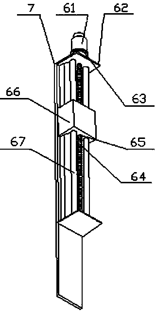
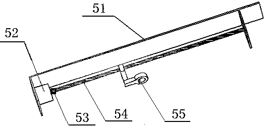
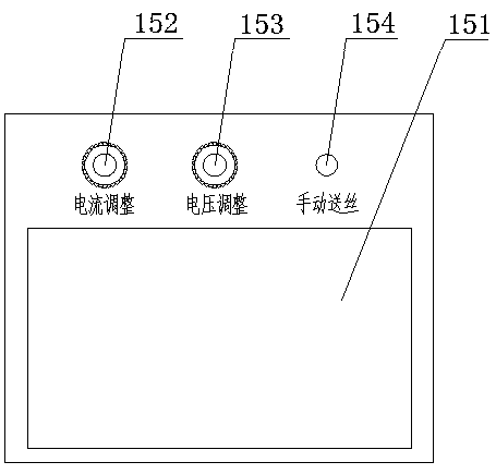
[0019] Such as figure 1 As shown, the automatic surfacing welding machine for the inner and outer walls of the wear-resistant ring includes an electric control box 1, a spindle box 2, a quick positioning three-jaw chuck 3, a welding torch 4, a horizontal feeding mechanism 5, a vertical lifting mechanism 6, a column 7, and a wire feeding mechanism 8. Welding wire 9, welding power source 10, base 14, touch screen 15, wherein, electric control box 1, spindle box 2 and column 7 are all installed on the base 14. The electric control box 1 is arranged on the left side of the spindle box 2, and a stepping motor controller 71 and a frequency converter 72 are arranged inside it. The motor controller 71 receives instructions input from the touch screen 15 to control the X-axis step of the horizontal feed mechanism 5. The motor 52 and the Y-axis stepp...


PUM


Abstract

The invention relates to an automatic surfacing welding machine for the inner and outer walls of a wear ring and a control system for automatic surfacing welding of the inner and outer walls of the wear ring. The automatic surfacing welding machine includes an electric cabinet, a spindle box, a quick positioning three-jaw chuck, a welding gun, a horizontal feeding mechanism, a vertical lifting mechanism, a stand column, a wire feeding mechanism, a welding wire, a welding power source, a base and a touch screen. The control system includes the electric cabinet, a spindle motor arranged in the spindle box for controlling the rotational speed of the quick positioning three-jaw chuck, an X-axis stepping motor arranged in the horizontal feeding mechanism for controlling the left and right movement of the welding gun, a Y-axis stepping motor arranged in the vertical lifting mechanism for controlling the up and down movement of a sliding plate, the wire feeding mechanism, the welding power source, a cooling water tank and the touch screen. By using the automatic surfacing welding machine for the inner and outer walls of the wear ring and the control system for automatic surfacing weldingof the inner and outer walls of the wear ring, the inner and outer diameter surface welding and the surface frame edge welding of the wear ring can be completed at one time, the technical performanceof products can be effectively improved, the production efficiency can be greatly improved, and therefore, the automatic surfacing welding machine for the inner and outer walls of the wear ring and the control system for automatic surfacing welding of the inner and outer walls of the wear ring are widely applied to both sides of the inner and outer diameter of an annular workpiece and various welding processes.

Description

technical field [0001] The invention relates to the technical field of special welding equipment for ring surfacing, in particular to an automatic surfacing machine for inner and outer walls of wear-resistant rings. The invention also relates to a control system for automatic surfacing welding of the inner and outer walls of the wear-resistant ring. Background technique [0002] In the prior art, the surfacing welding of the wear-resistant ring is carried out by manual surfacing operation, which has the following defects: ① the thickness of the surfacing layer is uneven, the size error is large, and the welding quality is difficult to meet the standard; The requirements are relatively high; ③ welders have high labor intensity and low work efficiency; ④ the working environment is poor, and the arc light and smoke generated during welding will cause harm to the welder's body. Contents of the invention [0003] The purpose of the present invention is to overcome the above de...

Claims


Application Information

Patent Timeline
IPC IPC(8): B23K9/04B23K9/10B23K9/28
CPCB23K9/04B23K9/10B23K9/287
Inventor 刘键王祖胜
Owner ZHUZHOU ZHENXIANG IND CO LTD
Learn More