Contact-free workpiece surface quality inspection device

A technology for workpiece surface and quality inspection, applied in measuring devices, optical devices, instruments, etc., can solve the problems of unqualified workpiece separation and transmission, workpiece scratches, affecting electroplating quality, etc., to improve practicability and performance, The effect of improving efficiency and speed

Pending Publication Date: 2022-04-05
镇江锦兴表面工程技术有限公司
View PDF0 Cites 0 Cited by
  • Summary
  • Abstract
  • Description
  • Claims
  • Application Information

AI Technical Summary

Problems solved by technology

[0004] In view of the above situation, in order to overcome the defects of the prior art, the present invention provides a contact-free workpiece surface quality inspection device, which effectively solves the problem that the existing workpiece surface quality inspection equipment and the surface contact detection of the workpiece easily cause scratches to the workpiece. It affects the quality of electroplating, and at the same time, the inspection equipment cannot separate and transmit the unqualified workpieces detected

Method used


Image

  • Contact-free workpiece surface quality inspection device
  • Contact-free workpiece surface quality inspection device
  • Contact-free workpiece surface quality inspection device

Examples


Embodiment 1

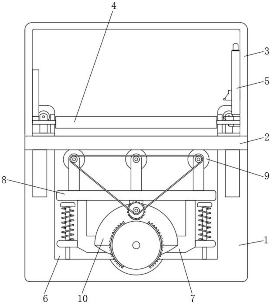
[0036] Embodiment one, by Figure 1 to Figure 8 Given, the present invention includes a fixed plate 2 fixedly installed on one side of the base 1, an n-shaped frame 3 fixedly installed on the top of the fixed plate 2, and two first rollers 4 installed on the lower part of the inner side of the n-shaped frame 3, n The middle part of the inner lower part of the shaped frame 3 is equipped with a test end 5, the test end 5 is located between the two first rollers 4, the middle part of the base 1 is provided with a groove 6, and the bottom of the groove 6 is equipped with a U-shaped lifting plate 7, A mounting plate 8 is fixedly installed between the tops of the U-shaped lifting plate 7, and a transmission assembly 9 is installed between both sides of the mounting plate 8 top, and a power end 10 is installed in the middle of the U-shaped lifting plate 7, and the two sides of the power end 10 The ends are respectively connected to the two transmission components 9 by transmission; ...

Embodiment 2

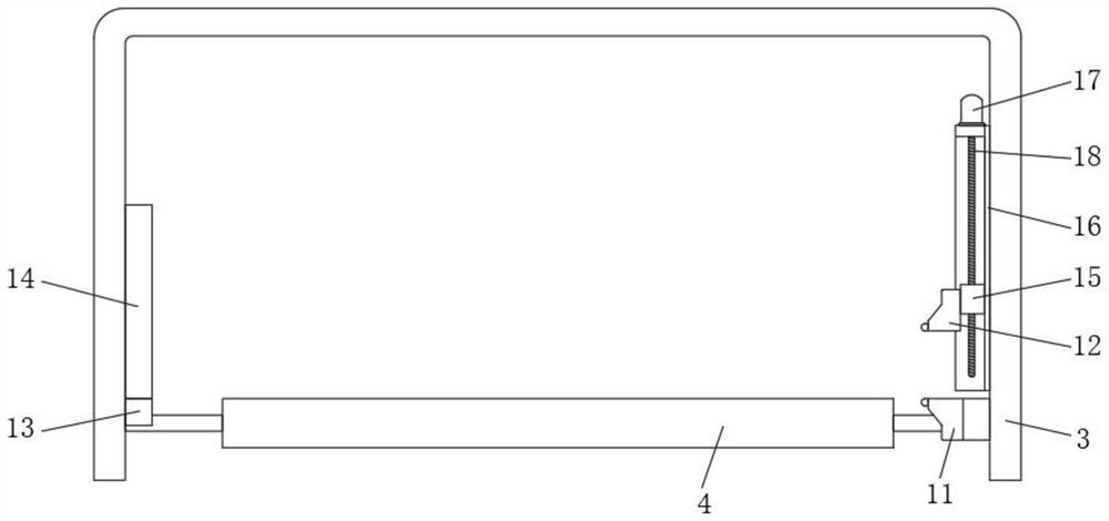
[0040] Embodiment two, on the basis of embodiment one, by figure 2 Provided, the inspection terminal 5 includes a fixed infrared ray transmitter 11, a mobile infrared ray transmitter 12, a first infrared receiver 13 and a second infrared receiver 14, and the fixed infrared transmitter 11 and the mobile infrared transmitter 12 are installed on the n-shaped frame 3 The bottom of the inner two sides, the first infrared receiving end 13 and the second infrared receiving end 14 are installed in the middle of both sides of the n-shaped frame 3, the fixed infrared emitting end 11 and the mobile infrared emitting end 12 and the first infrared receiving end 13 and The second infrared receiving end 14 is a dislocation installation, and the fixed infrared emitting end 11, the mobile infrared emitting end 12, the first infrared receiving end 13 and the second infrared receiving end 14 are all controlled by the controller, and the detected information is all transmitted to the controller. ...

Embodiment 3

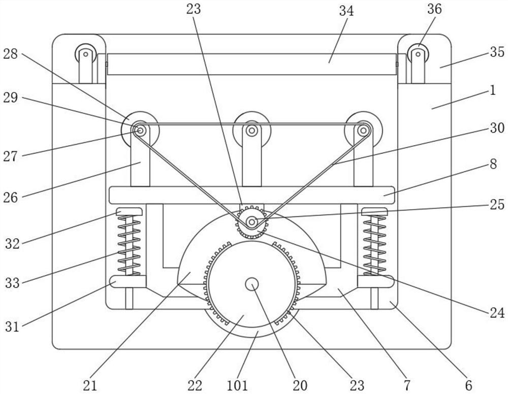
[0042] Embodiment three, on the basis of embodiment one, by Figure 3 to Figure 5 as well as Figure 7 and Figure 8 Given, the power end 10 includes a double output shaft motor 19, two rotating shafts 20 and two jacking discs 21, the double output shaft motor 19 is installed in the middle of the U-shaped lifting plate 7, and the two rotating shafts 20 are installed on the double output shaft motor 19, and one end of the rotating shaft 20 respectively extends to the two ends of the U-shaped lifting plate 7 and is fixedly connected with two jacking plates 21, so that the U-shaped lifting plate 7 can be effectively adjusted; the jacking plate 21 includes The half disc 2101 and the crescent plate 2102, the crescent plate 2102 is fixedly installed in the middle of the half disc 2101, and the half disc 2101 and the crescent plate 2102 are all fixedly installed on the end of the rotating shaft 20, the arc surface of the crescent plate 2102 and the concave The bottom of the groove ...


PUM


Abstract

The invention relates to the technical field of workpiece surface quality inspection equipment, and discloses a contact-free workpiece surface quality inspection device, which solves the problem that the electroplating quality is affected due to the fact that workpieces are easily scratched when the conventional workpiece surface quality inspection equipment is in contact with the surfaces of the workpieces for detection. The device comprises a base, a fixing plate is fixedly installed on one side of the base, an n-shaped frame is fixedly installed on the top of the fixing plate, two first rollers are rotatably installed on the lower portion of the inner side of the n-shaped frame, and an inspection end is installed in the middle of the lower portion of the inner side of the n-shaped frame. The inspection end is located between the two first rollers, a groove is formed in the middle of the base, and a U-shaped lifting plate is installed at the bottom of the groove; the workpiece surface quality inspection equipment can detect workpieces without being in contact with the surfaces of the workpieces, meanwhile, the equipment can separate and convey unqualified workpieces in the detection process, and the practicability and the use performance of the equipment are effectively improved.

Description

technical field [0001] The invention belongs to the technical field of workpiece surface quality inspection equipment, in particular to a contact-free workpiece surface quality inspection device. Background technique [0002] Workpiece electroplating is the process of plating a thin layer of other metals or alloys on the surface of some metal workpieces or workpieces made of other materials using the principle of electrolysis. It uses electrolysis to make the surface of metal workpieces or workpieces made of other materials adhere The process of a layer of metal film; electroplating can improve the wear resistance, conductivity, light reflection, corrosion resistance (copper sulfate, etc.) and enhance the appearance of the workpiece. [0003] Before the workpiece is electroplated, the flatness of its surface needs to be tested. If the surface of the workpiece is uneven, it will affect the uniformity of the electroplating layer and the quality of the electroplating of the wor...

Claims


Application Information

Patent Timeline
IPC IPC(8): G01B11/30
Inventor 张晓
Owner 镇江锦兴表面工程技术有限公司
Why Eureka
Try Eureka