
Three-axis acceleration sensor correction method

A technology of axis acceleration and correction method, which is applied in the testing/calibration of speed/acceleration/shock measurement equipment, speed/acceleration/shock measurement, instruments, etc., which can solve the difficulty of batch calibration calculation and sample data acquisition of three-axis acceleration sensors. Large size, extremely high sample data requirements, etc., to achieve the effect of fast calculation speed, low cost and high accuracy

Pending Publication Date: 2022-04-05
CHENGDU LUXINGTONG INFORMATION TECH
View PDF0 Cites 1 Cited by
  • Summary
  • Abstract
  • Description
  • Claims
  • Application Information

AI Technical Summary

Problems solved by technology

The instrument method requires the help of external instruments, usually through the calibration of the calibration parameters with the help of precision instruments. This method is difficult to perform batch calibration calculations on a large number of three-axis acceleration sensors in practical applications, and this method is less sensitive to the user's perception. Calibration and calculation of the three-axis acceleration sensor is also costly; the common gravity reference calibration method has extremely high requirements for sample data, which is usually sample data obtained in an ideal environment. In practical applications, it is difficult to obtain sample data and cannot be quickly Problems with Batch Calibration

Method used


Image

  • Three-axis acceleration sensor correction method
  • Three-axis acceleration sensor correction method
  • Three-axis acceleration sensor correction method

Examples


Embodiment 1

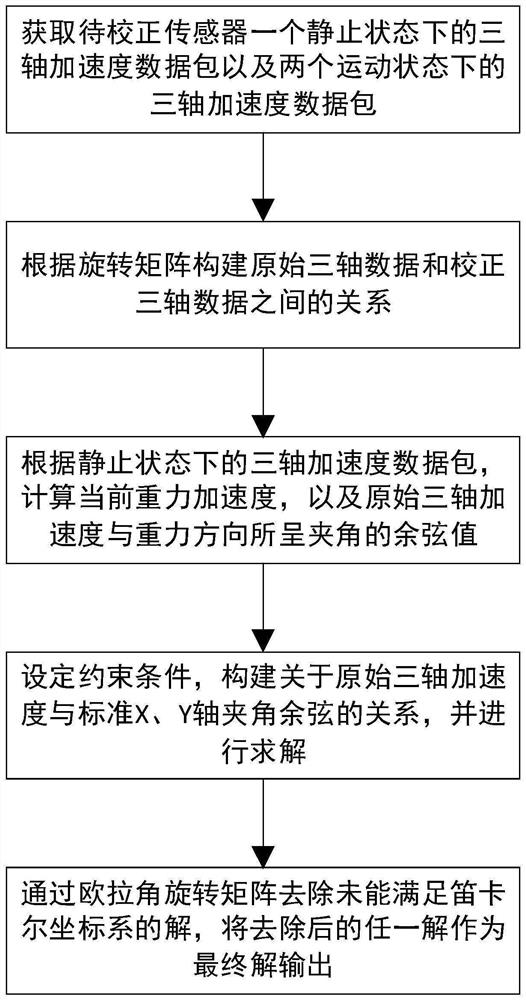
[0031] Embodiment 1 of the present invention discloses a three-axis acceleration sensor calibration method, which is based on the gravity reference calibration and the correction coefficient solution algorithm of random motion point data. The three-axis acceleration data package in the motion state, based on the vector summation operation, solves the angle between the original three-axis acceleration of the sensor and the three-axis acceleration under the standard attitude, a total of nine correction coefficients, and calculates the rotation matrix And the way of associating other speed change point data packets to filter out the correct correction coefficient.

[0032] In this embodiment, a three-axis acceleration sensor mounted on a vehicle is taken as an example for illustration;

[0033] Define the positive direction of the x-axis of the three-axis acceleration sensor after correction as the forward direction of the vehicle, the positive direction of the y-axis as the left...

Embodiment 2

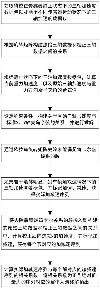
[0104] Embodiment 2 of the present invention discloses a three-axis acceleration sensor calibration method, such as figure 2 As shown, it includes S1-S6, wherein the specific content of steps S1-S5 is as described in the above-mentioned embodiment 1, and will not be repeated here.

[0105] Similarly, the data parameters in the above-mentioned embodiment 1 are still used for description.

[0106] In this embodiment, step S6 is disclosed: verifying the shifting direction according to the forward direction of the vehicle, and outputting the verified correct solution as the final correction coefficient; the details are as follows:

[0107] Collect 30 or more data packets, which can clearly identify the three-axis acceleration data packets in the case of vehicle acceleration and deceleration, and mark the acceleration or deceleration. The acceleration is recorded as 1, and the deceleration is recorded as -1, and the actual value containing the marked value is obtained. Accelerati...


PUM


Abstract

The invention provides a three-axis acceleration sensor correction method. The three-axis acceleration sensor correction method comprises the steps of S1, acquiring a three-axis acceleration data packet of a sensor to be corrected in a static state and data packets of the sensor to be corrected in two motion states; s2, constructing a relationship between the original three-axis data and the corrected three-axis data according to the rotation matrix; s3, calculating the current gravitational acceleration and the cosine value of the included angle between the original three-axis acceleration and the gravity direction; s4, constraint conditions are set, and the relation between the original three-axis acceleration and the cosine of the included angle of the standard X axis and the cosine of the included angle of the standard Y axis is established for solving; s5, removing solutions which cannot meet the Cartesian coordinate system through an Euler angle rotation matrix; and finally, verifying the residual solution, and outputting a final solution. According to the method, the correction coefficient of the relation model is calculated and constructed based on the gravity reference calibration and the random motion point data, so that rapid, accurate and efficient correction of the three-axis acceleration sensor is realized.

Description

technical field [0001] The invention relates to the technical field of three-axis acceleration sensor calibration, in particular to a three-axis acceleration sensor calibration method. Background technique [0002] The three-axis acceleration sensor is a device for measuring spatial acceleration based on the basic principle of acceleration. The device is small in size and light in weight, and can fully and accurately reflect the motion properties of objects. It is widely used in aerospace, robotics, automobiles, and medicine. Applications. [0003] In the manufacture of three-axis acceleration sensors, due to factors such as manufacturing process, physical properties of manufacturing materials, and equipment installation, different three-axis acceleration sensors have different parameters, and there is a common problem that there is an obvious angle between them and the standard attitude axis. , these problems will produce huge errors in the process of analyzing and simulat...

Claims


Application Information

Patent Timeline
Patent Type & Authority Applications(China)
IPC IPC(8): G01P21/00
Inventor 梁玉婷丁文忠陈锐
Owner CHENGDU LUXINGTONG INFORMATION TECH
Learn More