Supercharge Your Innovation With Domain-Expert AI Agents!

Box-type energy storage battery system

A technology of energy storage battery and battery system, applied in the direction of secondary battery, battery pack parts, secondary battery repair/maintenance, etc., can solve problems such as affecting the normal operation of power station, high maintenance and operation cost, difficult site selection and construction site, etc. , to solve the thermal runaway spread in the system, improve operational safety and convenience, and improve volume utilization.

Pending Publication Date: 2022-04-05
SHANGHAI RUIPU ENERGY CO LTD
View PDF20 Cites 4 Cited by
  • Summary
  • Abstract
  • Description
  • Claims
  • Application Information

AI Technical Summary

Problems solved by technology

Because traditional power stations have huge investment costs in the pre-construction planning, site selection, design, engineering construction, installation, maintenance, and operation, and it is difficult to find suitable sites for construction sites; A variety of large-scale solar, wind, and tidal energy power generation systems have been installed, and corresponding energy storage power stations have been configured to store the electric energy converted from solar energy or wind energy through energy storage batteries to meet the electricity needs of residents.
[0003] However, the current traditional power stations all need to build fixed concrete station buildings. This kind of station building occupies a large area and cannot be moved. It requires personnel to guard and inspect for a long time, and the maintenance and operation costs are high.
In addition, there are multiple battery packs placed in the traditional power station. When the power station is running, the battery pack will generate huge heat. If the heat cannot be discharged in time, it will bring safety hazards to the power station and affect the normal operation of the power station.

Method used


Image

  • Box-type energy storage battery system
  • Box-type energy storage battery system
  • Box-type energy storage battery system

Examples


Embodiment Construction

[0050] The present invention will be described in detail below in conjunction with specific embodiments. The following examples will help those skilled in the art to further understand the present invention, but do not limit the present invention in any form. It should be noted that those skilled in the art can make several changes and improvements without departing from the concept of the present invention. These all belong to the protection scope of the present invention.

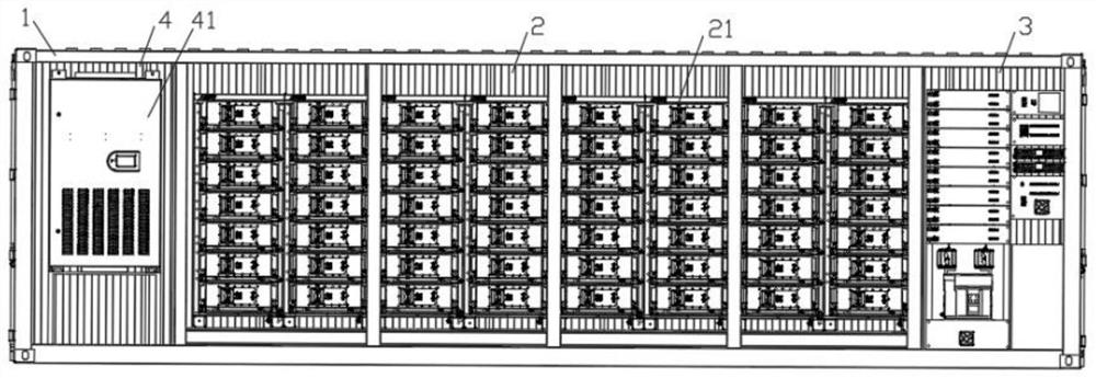
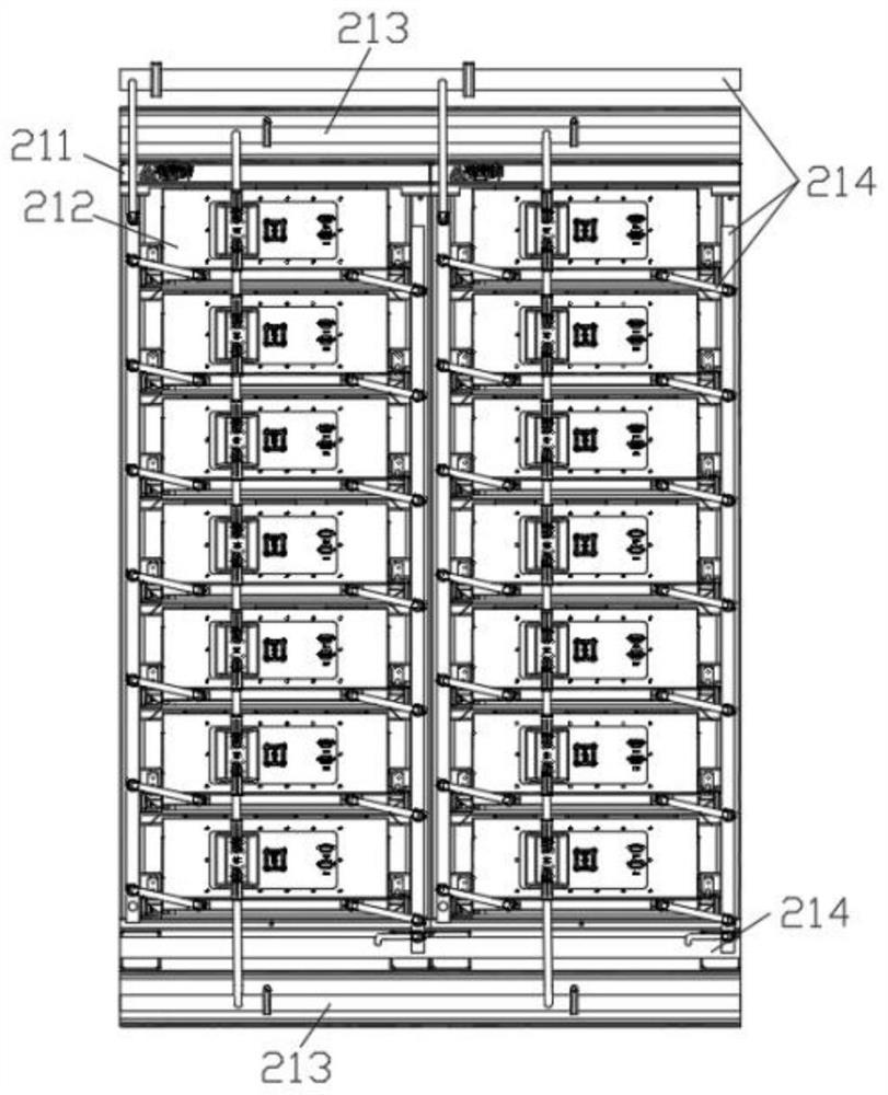
[0051] Such as figure 1 Shown is the front schematic diagram of the box-type energy storage battery system, such as Figure 15 Shown is the internal schematic diagram of the box-type energy storage battery system, including a container for integrating the installation carrier, and the container includes a battery compartment 2 , an electrical compartment 3 and a liquid-cooled engine compartment 4 . The battery compartment 2 is provided with a battery cluster 21, such as figure 2 Shown is a schematic ...


PUM


Abstract

The invention provides a box-type energy storage battery system in the technical field of energy storage batteries, which comprises a container for integrated installation of a carrier, and the container comprises a battery cabin, an electrical cabin and a liquid cooling cabin; a battery cluster is arranged in the battery cabin, the battery cluster comprises a battery system, mounting brackets and a liquid cooling pipeline system, the mounting brackets are fixedly arranged in the container, the battery system is arranged between the mounting brackets, the liquid cooling pipeline system is connected with the battery system, the liquid cooling pipeline system comprises a plurality of pipelines, and the plurality of pipelines extend to the battery cabin; the electrical cabin comprises an electrical control system for controlling each battery branch, and the electrical control system is connected with the battery cluster; the liquid cooling cabin comprises a liquid cooling unit, and the liquid cooling unit is connected with the other end of the liquid cooling pipeline system. The battery cabin is arranged between the liquid cooling unit cabin and the electrical cabin, a waterway and a circuit are managed separately, the depth space of the electrical cabin is fully utilized, the cabin space utilization rate is improved, and installation and replacement of a single subrack module are facilitated.

Description

technical field [0001] The present invention relates to the technical field of energy storage batteries, in particular to a box-type energy storage battery system. Background technique [0002] At present, there is a shortage of electricity in plateau, alpine, and island areas, and areas with inconvenient transportation are not suitable for the construction of traditional power stations. Because traditional power stations have huge investment costs in the pre-construction planning, site selection, design, engineering construction, installation, maintenance, and operation, and it is difficult to find suitable sites for construction sites; A variety of large-scale solar, wind, and tidal energy power generation systems have been installed, and corresponding energy storage power stations have been configured to store the electric energy converted from solar energy or wind energy through energy storage batteries to meet the electricity needs of residents. [0003] However, the c...

Claims


Application Information

Patent Timeline
IPC IPC(8): H01M50/289H01M10/42H01M10/48H01M10/613H01M10/6568H01M50/244
CPCY02E60/10
Inventor 郁辰刘思王思远侯敏曹辉
Owner SHANGHAI RUIPU ENERGY CO LTD
Features
  • R&D
  • Intellectual Property
  • Life Sciences
  • Materials
  • Tech Scout
  • Unparalleled Data Quality
  • Higher Quality Content
  • 60% Fewer Hallucinations
Learn More