Method for improving power transmission capability of grid-connected inverter under extremely weak power grid
A power transmission and inverter technology, applied in reactive power compensation, photovoltaic power generation, AC network voltage adjustment, etc., can solve problems such as insufficient power transmission capacity of grid-connected inverters, improve power transmission capacity, and expand output current The effect of the cap
- Summary
- Abstract
- Description
- Claims
- Application Information
AI Technical Summary
Problems solved by technology
Method used
Image
Examples
specific Embodiment approach 1
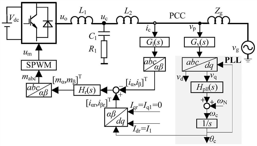
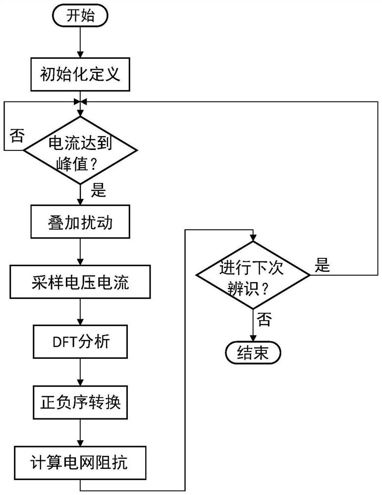
[0027] Specific implementation mode one: combine figure 1 with figure 2 Describe this implementation mode, a method for improving the power transmission capacity of a grid-connected inverter under an extremely weak grid described in this implementation mode, the method includes the following content:
[0028] Step 1. Collect the common coupling point voltage v p Input the voltage sampling function, the output value is transformed by the Parker converter, and the d-axis component v of the common coupling point voltage is obtained d and the common coupling point voltage q-axis component v q ;
[0029] Step 2. Common coupling point voltage q-axis component v d After the proportional-integral controller, the obtained value is consistent with the given angular frequency ω N The sum is obtained to obtain the output angular frequency ω of the phase-locked loop c Send it to the integration link to get the output phase θ of the phase-locked loop c , the output phase θ of the PL...
specific Embodiment approach 2
[0039] Embodiment 2: This embodiment is to further limit the method for improving the power transmission capacity of grid-connected inverters under extremely weak power grids described in Embodiment 1. In this embodiment, it is characterized in that the reactive power compensation coefficient K d Expressed as:
[0040]
[0041] In the formula, V g is the grid voltage amplitude, I 1 is the given value of inverter d-axis current, X g is the grid impedance.
specific Embodiment approach 3
[0042] Specific Embodiment 3: This embodiment further limits the method for improving the power transmission capacity of grid-connected inverters under extremely weak power grids described in Specific Embodiment 2. In this embodiment, the inverter output current q-axis refers to Value I qr Expressed as:
[0043] I qr =(v d -V g )K d G df (s) Formula 2,
[0044] In the formula, I qr is the inverter output current q-axis reference value, v d is the q-axis component of the common coupling point voltage, K d is the reactive power compensation coefficient, G df (s) is a low-pass filter.
[0045] In this embodiment, the PCC voltage amplitude information is introduced into the q-axis current reference quantity of the inverter current loop to realize feedforward control, and the reference quantity is changed from 0 to: I qr =(v d -V g )K d G df (s); I qr is the inverter output current q-axis reference value, v d is the d-axis component of the PCC voltage, that is, i...
PUM
 Abstract
Description
Claims
Application Information
 - R&D
- Intellectual Property
- Life Sciences
- Materials
- Tech Scout
- Unparalleled Data Quality
- Higher Quality Content
- 60% Fewer Hallucinations
Browse by: Latest US Patents, China's latest patents, Technical Efficacy Thesaurus, Application Domain, Technology Topic, Popular Technical Reports.
© 2025 PatSnap. All rights reserved.Legal|Privacy policy|Modern Slavery Act Transparency Statement|Sitemap|About US| Contact US: help@patsnap.com


