Microphotography equipment and method

A photographic equipment and macro technology, which is applied to the parts and electrical components of TVs and color TVs. Simple structure and the effect of increasing the irradiation area

Pending Publication Date: 2022-04-05
YANCHENG TEACHERS UNIV
View PDF0 Cites 2 Cited by
  • Summary
  • Abstract
  • Description
  • Claims
  • Application Information

AI Technical Summary

Problems solved by technology

Especially when performing macro shooting on a moving target object, compared with a stationary object, it is necessary to repeatedly focus on the moving target object to obtain the best shooting effect, which increases the accuracy of the moving target object. It is difficult to take macro shots of the target object, and the adjusted focus is easy to blur with the movement of the target object, and it is difficult to obtain the best shooting effect

Method used


Image

  • Microphotography equipment and method
  • Microphotography equipment and method

Examples


Embodiment 1

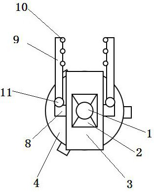
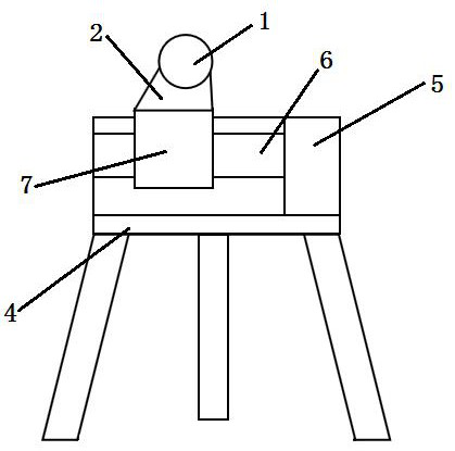
[0029] Such as figure 1 and figure 2 Shown, a kind of macro photography equipment, it comprises pan-tilt assembly, CMOS lens assembly 1, support 4;

[0030] Described cloud platform assembly comprises base 3, the cloud platform 2 that can rotate 360 ​​degrees, the cloud platform control system, described base 3 is provided with motor 5, and one side of described motor 5 is provided with lead screw 6, and described lead screw One end of 6 is connected with the rotating shaft of described motor 5, and the other end of described leading screw 6 is connected with base 3 through bearing, and described leading screw 6 is provided with the leading screw nut 7 that cooperates with each other, and the leading screw nut 7 of described leading screw The top is connected with the bottom of the cloud platform 2; the bottom of the base 3 is connected with the support 4, the control system is installed on one side of the base 3, and the cloud platform control system is connected with the m...

Embodiment 2

[0034] A method for macro photography of dynamic objects, such as being used to take clear pictures of the transient time when the object changes from stillness to motion, it comprises the following steps:

[0035] (1) Arrange the macro photography equipment described in Embodiment 1 according to the position of the object to be photographed, and then input the preset optical parameters to the lens central control system to pre-photograph the object to be photographed, and the image processing system will process the received image The information is processed, 5 regions are randomly selected for marking, and the coordinate data of each region is read (a n , b n ), where n is a natural number; then the distance data between each area is calculated and stored in the data storage module; the area is composed of 10 to 100 adjacent pixels; the optical parameters include but are not limited to the focus range , aperture range, exposure level, focal length range and shutter speed; ...


PUM


Abstract

The invention discloses a macro photographic device which comprises a holder assembly, a CMOS lens assembly and a support. The holder assembly comprises a base, a holder capable of rotating by 360 degrees and a holder control system. Light supplementing devices are arranged on the two sides of the holder. Each light supplementing device comprises a fixing block and an arc-shaped plate provided with an LED lamp. The CMOS lens assembly is mounted on the holder and comprises an aperture and an aperture automatic adjusting device which are matched with each other, a CMOS image sensor, an image processing system, a lens central control system and a lens base; the image processing system comprises a data storage module, a data receiving module, a data sending module, a data processing module and a convolutional neural network module; the lens base is used for fixing the aperture, the aperture automatic adjusting equipment, the CMOS image sensor and the image processing system; and the bottom of the lens base is connected with the holder. The device is suitable for carrying out macro shooting on a static or dynamic object, and the best shooting effect can be obtained.

Description

technical field [0001] The invention belongs to the technical field of macro photography, and in particular relates to a macro photography equipment and method. Background technique [0002] Macro photography refers to the optical ability of a camera to capture an image that is as large as or slightly smaller than the actual object through the optical ability of the lens. Macro shooting can turn ordinary scenes into dramatic ones. Macro is especially good at expressing small things such as flowers, birds, fish and insects. It can fully display the details, and you can express yourself in topic selection, composition, and lighting as you like. Creativity in terms of photography is not like shooting scenery, people, folk culture and other subjects, which are subject to many conditions. [0003] As we all know, focusing is a crucial step in the shooting process, and it is also true for macro photography, because macro photography is all about scenes with extremely small spatia...

Claims


Application Information

Patent Timeline
Patent Type & Authority Applications(China)
IPC IPC(8): H04N5/225H04N5/232H04N5/374
Inventor 王帅
Owner YANCHENG TEACHERS UNIV
Why Eureka
Try Eureka