Composite die pipe for alloy ingot pouring

A composite mold and alloy ingot technology, applied in the field of superalloy smelting, can solve the problems of slow solidification of molten steel, low heat dissipation efficiency, uneven composition of alloy ingots, etc., to improve surface quality and purity, improve composition uniformity, The effect of improving the quality of the inner surface

Pending Publication Date: 2022-04-08
JIANGSU LONGDA SUPERALLOY MATERIAL CO LTD
View PDF0 Cites 0 Cited by
  • Summary
  • Abstract
  • Description
  • Claims
  • Application Information

AI Technical Summary

Problems solved by technology

In the normal production process, the following main problems often exist in the formwork, pouring process and demoulding: (1) The mold tube is long, and it is difficult to clean and inspect the inner surface. If there are inclusions or pits on the inner surface, it will cause The number of inclusions in the prepared alloy ingot increases, and there are problems such as pinholes, cold shuts, and difficult demoulding on the surface of the alloy ingot; (2) The wall of the mold tube is thin, the heat of the alloy liquid is transferred through radiation, the heat dissipation efficiency is low, and the solidification speed of the molten steel is slow , eventually lead to uneven composition of the alloy ingot, or even serious segregation problems; (3) pouring alloys with higher temperatures will cause serious scalding problems, resulting in the reaction of the alloy ingot with the mold tube due to the scalding, and the product composition deviates from the technical requirements If it is scrapped, the corresponding mold tube will also be scrapped, and at the same time, it brings great difficulties to the demoulding of the alloy ingot; (4) the mold tube has been poured and used under high temperature conditions for many times, and the bending phenomenon is serious. If it is used again, it needs to be rectified again. Straight, reduces production efficiency and increases production cost

Method used


Image

  • Composite die pipe for alloy ingot pouring
  • Composite die pipe for alloy ingot pouring
  • Composite die pipe for alloy ingot pouring

Examples


Embodiment 1

[0021] Embodiment 1 (preparation of φ 50mm master alloy ingot)

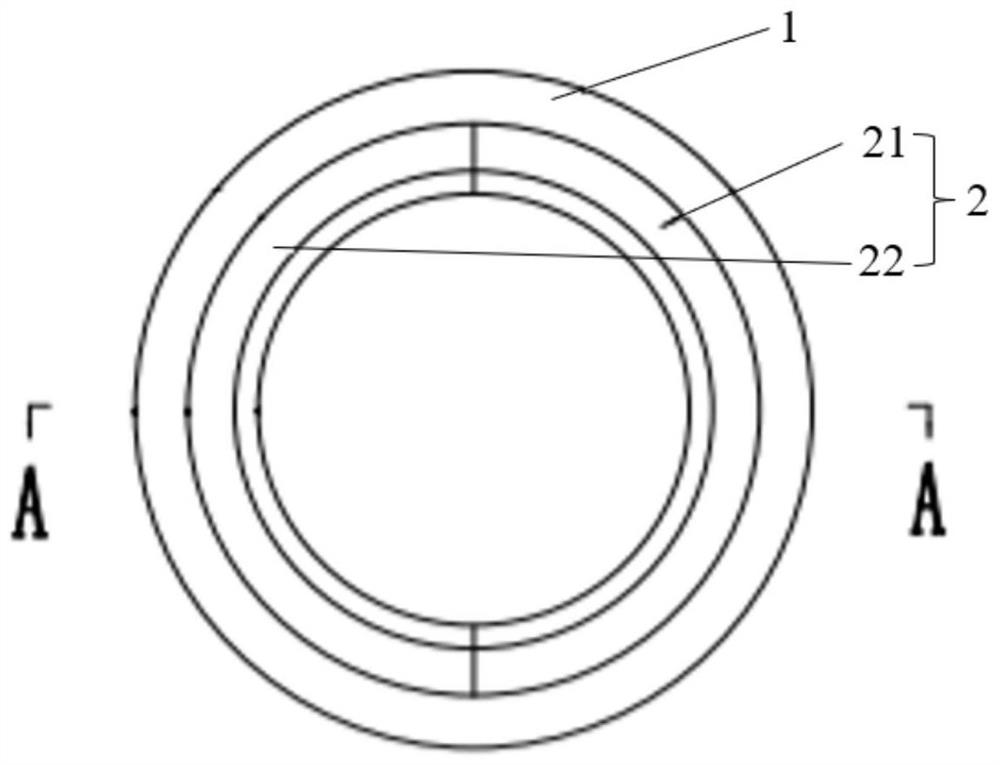
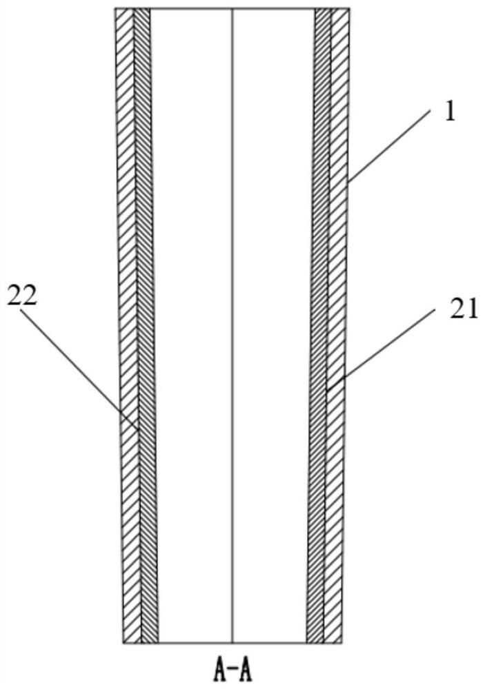
[0022] Such as figure 1 and 2 Shown, a kind of composite mold tube for alloy ingot pouring, described composite mold tube comprises outer layer cylindrical mold tube 1 and inner layer cylindrical mold tube 2, and described inner layer cylindrical mold tube 2 consists of two The semicircular mold tube 21, 22 is composed of, the inner cylindrical mold tube 2 is arranged inside the outer cylindrical mold tube 1, and the outer surface of the inner cylindrical mold tube 2 and the outer layer The inner surface of the cylindrical mold tube 1 is in close contact with each other.

[0023] The outer cylindrical mold tube 1 and the inner cylindrical mold tube 2 are made of carbon steel.

[0024] The length of the outer cylindrical mold tube 1 and the inner cylindrical mold tube 2 is 800mm, the wall thickness is 5mm, the taper is 0°, and the inner diameter of the two semicircular inner wall mold tubes is 50mm.

[0025] T...

Embodiment 2

[0028] Embodiment 2 (preparation of φ80mm master alloy ingot)

[0029] A composite mold tube for casting alloy ingots, the composite mold tube includes an outer cylindrical mold tube 1 and an inner cylindrical mold tube 2, and the inner cylindrical mold tube 2 consists of two semicircular mold tubes Die tube 21, 22 is formed, and described inner cylindrical mold tube 2 is arranged on the inside of described outer cylindrical mold tube 1, and the outer surface of described inner cylindrical mold tube 2 and outer cylindrical shape The inner surface of the mold tube 1 is in close contact with each other.

[0030] The outer cylindrical mold tube 1 and the inner cylindrical mold tube 2 are made of carbon steel.

[0031] The length of the outer cylindrical mold tube 1 and the inner cylindrical mold tube 2 is 1000mm, the wall thickness is 5mm, the taper is 1°, and the inner diameter of the two semicircular inner wall mold tubes is 80mm.

[0032] The inner surface roughness of the o...

Embodiment 3

[0036] Embodiment 3 (preparation of φ 120mm master alloy ingot)

[0037] A composite mold tube for casting alloy ingots, the composite mold tube includes an outer cylindrical mold tube 1 and an inner cylindrical mold tube 2, and the inner cylindrical mold tube 2 consists of two semicircular mold tubes Die tube 21, 22 is formed, and described inner cylindrical mold tube 2 is arranged on the inside of described outer cylindrical mold tube 1, and the outer surface of described inner cylindrical mold tube 2 and outer cylindrical shape The inner surface of the mold tube 1 is in close contact with each other.

[0038] The outer cylindrical mold tube 1 and the inner cylindrical mold tube 2 are made of carbon steel.

[0039] The length of the outer cylindrical mold tube 1 and the inner cylindrical mold tube 2 is 900mm, the wall thickness is 5mm, the taper is 0°, and the inner diameter of the two semicircular inner wall mold tubes is 120mm.

[0040] The inner surface roughness of the...


PUM

PropertyMeasurementUnit
The inside diameter ofaaaaaaaaaa
Roughnessaaaaaaaaaa
Roughnessaaaaaaaaaa

Abstract

The invention belongs to the technical field of alloy smelting preparation, and particularly relates to a composite die pipe for alloy ingot pouring. The composite die pipe comprises an outer-layer cylindrical die pipe and an inner-layer cylindrical die pipe, the inner-layer cylindrical die pipe is composed of two semicircular die pipes, the inner-layer cylindrical die pipe is arranged in the outer-layer cylindrical die pipe, and the outer surface of the inner-layer cylindrical die pipe is tightly attached to the inner surface of the outer-layer cylindrical die pipe. The cylindrical outer-layer die pipe and the two semicircular inner-layer die pipes have the same taper and length, and the two semicircular inner-layer die pipes are mutually independent and can be replaced independently. According to the composite die pipe for alloy ingot pouring, on one hand, the purity of the alloy ingot can be improved, component uniformity can be improved, component segregation can be reduced, on the other hand, the die cost can be saved, the service life of a die can be prolonged, the surface quality of the prepared alloy ingot can be improved, the demolding efficiency of the alloy ingot can be improved, and the labor cost can be saved.

Description

technical field [0001] The invention belongs to the technical field of high-temperature alloy smelting, and in particular relates to a composite mold tube for pouring alloy ingots. Background technique [0002] Cast superalloys are mainly used in the preparation of core hot-end parts of aero-engines and gas turbines. With the continuous improvement of performance requirements of aero-engines and gas turbines, higher requirements have been put forward for the inclusions, purity, and uniformity of cast superalloy master alloy ingots. requirements. Cast superalloy master alloy ingots are mainly prepared by melting in a vacuum induction furnace. The pre-smelting preparation involves the process of forming molds, including the combined installation of refractory risers, bottom pads and mold tubes; after the melting is completed, it involves demoulding processes, and the pouring is about to be completed. The alloy ingot comes out of the die tube. In the normal production process...

Claims


Application Information

Patent Timeline
IPC IPC(8): B22D7/06
Inventor 李华兵李淑苹王博浦益龙董鸿志李铭徐进涛
Owner JIANGSU LONGDA SUPERALLOY MATERIAL CO LTD
Why Eureka
Try Eureka