
A cable tray forming and welding machine

A technology of molding processing and cable tray, which is applied in the field of cable tray molding, processing and welding machines, can solve the problems of low cost, tilting of the main bridge frame and the barrier panel, and the influence of the product on the use of the product, so as to ensure the practicality and avoid the effect of tilting

Active Publication Date: 2022-05-17
江苏中复利光电科技有限公司
View PDF8 Cites 0 Cited by
  • Summary
  • Abstract
  • Description
  • Claims
  • Application Information

AI Technical Summary

Problems solved by technology

[0003] The forming process of the cable tray is mainly through the operator to place the main bridge of the cable tray on the workbench for clamping and fixing, and then the operator welds and fixes the multiple barrier plates inside it in sequence, and finally the formed cable tray is obtained. This kind of cable tray forming and processing method is widely used because of its low cost, but there are still the following problems: 1. The existing cable tray forming and processing welding machine has poor clamping stability for the main bridge frame and the barrier plate, which is easy to cause the main bridge frame and the barrier plate The barrier plate is in a tilted state during welding
[0004] 2. During the forming process of the existing cable tray, there will be misalignment between the front and rear ends of the main bridge frame and the barrier plate, so the processed products will affect the subsequent use, and the existing cable tray molding processing efficiency is slow, not good Can realize fast welding in the form of assembly line

Method used


Image

  • A cable tray forming and welding machine
  • A cable tray forming and welding machine
  • A cable tray forming and welding machine

Examples


Embodiment Construction

[0030] The following will clearly and completely describe the technical solutions in the embodiments of the present invention with reference to the accompanying drawings in the embodiments of the present invention. Obviously, the described embodiments are only some, not all, embodiments of the present invention. Based on the embodiments of the present invention, all other embodiments obtained by persons of ordinary skill in the art without making creative efforts belong to the protection scope of the present invention.

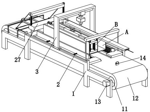
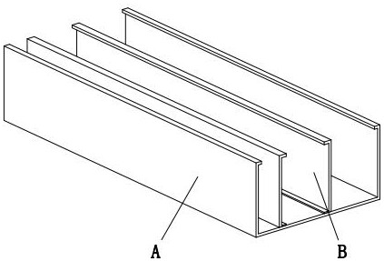
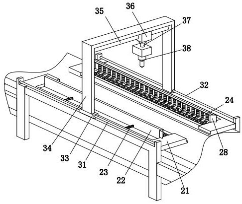
[0031] refer to figure 1, a cable tray forming and processing welding machine, comprising a placement frame 1, a clamping device 2 and a welding device 3, the upper end of the placement frame 1 is provided with a clamping device 2, and the top of the clamping device 2 is provided with a welding device 3, The welding device 3 is set on the upper end of the placing frame 1; the main body of the cable bridge is a main bridge A with a 匚-shaped structure, and two b...


PUM


Abstract

The invention proposes a welding machine for forming and processing cable trays, which relates to the field of welding processing technology, and includes a placing frame, a clamping device and a welding device. The upper end of the placing frame is provided with a clamping device, and the placing frame is provided with a welding device. The top of the clamping device, in addition the present invention can solve the following problems: a. The existing cable tray forming welding machine has poor clamping stability to the main bridge and the barrier plate, which easily causes the main bridge and the barrier plate to be blocked in the welding process The board is in an inclined state. b. During the forming process of the existing cable tray, there will be unevenness between the main bridge frame and the front and rear ends of the barrier plate, so the processed products will affect the subsequent use, and the existing cable tray molding processing efficiency is slow, not good It can realize fast welding in the form of assembly line.

Description

technical field [0001] The invention relates to the technical field of welding processing, and specifically proposes a welding machine for forming and processing cable trays. Background technique [0002] Cable trays are widely used in infrastructure construction such as industrial and agricultural production, transportation, etc., and are important supporting components for power supply supporting power transmission, telecommunication transmission, and cable laying. Cable trays are divided into trough type, tray type, ladder type, and grid type structure, among which the trough-type cable tray is widely used because of its dust-proof and anti-interference performance. [0003] The forming process of the cable tray is mainly through the operator to place the main bridge of the cable tray on the workbench for clamping and fixing, and then the operator welds and fixes the multiple barrier plates inside it in sequence, and finally the formed cable tray is obtained. This kind o...

Claims


Application Information

Patent Timeline
Patent Type & Authority Patents(China)
IPC IPC(8): B23K31/02B23K37/04
Inventor 张仁云
Owner 江苏中复利光电科技有限公司
Learn More