
Welding equipment for air inlet temperature and pressure sensor machining

A technology of pressure sensor and intake air temperature, which is applied in welding equipment, auxiliary welding equipment, metal processing equipment, etc., can solve the problems of affecting the normal operation of the equipment, poor environmental protection, and affecting the working environment, so as to meet the requirements of high-precision welding and improve Welding stability, the effect of improving product quality

Pending Publication Date: 2022-04-08
WUHAN FINEMEMS
View PDF0 Cites 0 Cited by
  • Summary
  • Abstract
  • Description
  • Claims
  • Application Information

AI Technical Summary

Problems solved by technology

[0005] In order to overcome the above-mentioned defects of the prior art, the present invention provides a welding equipment for processing the intake air temperature and pressure sensor, which solves the problem that a large amount of irritating high-temperature gas is easily generated during the welding process, which seriously affects the working environment and has certain potential safety hazards. It makes it less environmentally friendly, and at the same time, during the continuous welding process, the heat dissipation performance of the equipment is not good, and the long-term work affects the normal operation of the equipment; at the same time, when clamping the workpiece, most of them use double-head clamping to limit the workpiece , it is difficult to calibrate the position of the workpiece, there will still be a certain deviation in the alignment accuracy, and it is difficult to ensure the high-precision welding requirements of the sensor processing, thus affecting the quality of the product

Method used


Image

  • Welding equipment for air inlet temperature and pressure sensor machining
  • Welding equipment for air inlet temperature and pressure sensor machining
  • Welding equipment for air inlet temperature and pressure sensor machining

Examples


Embodiment Construction

[0030] The technical solution of this patent will be further described in detail below in conjunction with specific embodiments.

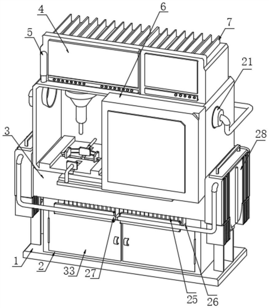
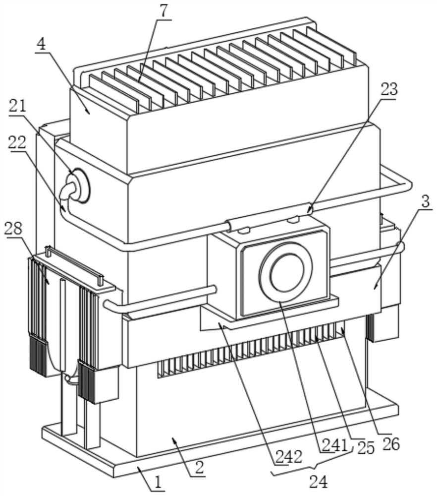
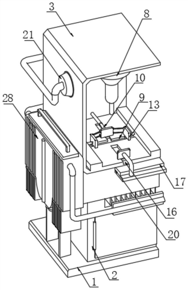
[0031] Such as Figure 1-6As shown, the present invention provides a technical solution: a welding device for processing an intake air temperature and pressure sensor, including a base plate 1, the upper surface of the base plate 1 is fixedly connected with the lower surface of the equipment box 2, and the upper surface of the equipment box 2 is welded to the lower surface of the equipment box 2. The lower surface of the platform 3 is fixedly connected, the upper surface of the welding platform 3 is provided with a control panel 4, the left side of the front of the control panel 4 is provided with a warning light 5, and the upper surface of the inner wall of the welding platform 3 is provided with three welding mechanisms 8, the welding mechanism 8 The bottom of the support assembly 10 is provided with a support assembly 10, the front of the inner ...


PUM


Abstract

The invention discloses welding equipment for air inlet temperature and pressure sensor machining, and belongs to the technical field of sensor machining. The welding equipment comprises a bottom plate, the upper surface of the bottom plate is fixedly connected with the lower surface of an equipment box, the upper surface of the equipment box is fixedly connected with the lower surface of a welding table, and a control panel is arranged on the upper surface of the welding table; a warning lamp is arranged on the left side of the front face of the control panel. According to the welding device, the bottom plate, the equipment box, the welding table, the welding mechanism, the supporting assembly, the side plates, the top plate, a sliding way and a spring are arranged, the welding stability of the welding device is effectively improved by limiting a workpiece in multiple directions, meanwhile, a baffle is in a movable state and is in linkage with the two side plates through a connecting rod, and the purpose of calibrating the workpiece in the clamping process is effectively achieved; the high-precision welding requirement of sensor machining is guaranteed, and the product quality is improved.

Description

technical field [0001] The invention belongs to the technical field of sensor processing, and in particular relates to a welding device for processing an intake air temperature and pressure sensor. Background technique [0002] Intake air pressure sensor, referred to as MAP, is connected to the intake manifold by a vacuum tube. With different speed loads of the engine, it senses the vacuum change in the intake manifold, and then converts the change of the internal resistance of the sensor into a voltage signal for the ECU. Correct the fuel injection quantity and ignition timing angle. The intake air pressure sensor used in the EFI engine to detect the intake air volume is called a D-type injection system (velocity density type). The intake air pressure sensor detects the intake air volume. Indirect detection is used instead of the direct detection of the sensor, and it is also affected by many factors. Therefore, there are many places different from the intake air flow of th...

Claims


Application Information

Patent Timeline
IPC IPC(8): B23K37/00B23K37/02B01D35/02
Inventor 王小平曹万王红明熊波梁世豪
Owner WUHAN FINEMEMS
Learn More