Tempering furnace air duct convenient to maintain and repair

A tempering furnace and air duct technology, applied in furnaces, heat treatment furnaces, furnace types, etc., can solve the problems of reduced tempering efficiency, single tempering furnace, inconvenient maintenance and disassembly, etc., to prevent heating expansion deformation and uneven heating , the effect of reducing the floor area

Pending Publication Date: 2022-04-08
SHANDONG HEIXUANFENG SAW IND
View PDF0 Cites 0 Cited by
  • Summary
  • Abstract
  • Description
  • Claims
  • Application Information

AI Technical Summary

Problems solved by technology

[0002] The use of tempering furnaces is very common now, but one of the most common disadvantages in the use of tempering furnaces is that the setting of the air inlet of the tempering furnace is relatively simple, and the air duct is directly into the furnace body, which leads to the concentration of the wind coming out of the air duct. The wind can hardly blow to the surrounding parts of the tempering furnace, which makes it difficult to control the temperature of the tempering furnace, which is not conducive to the use of the tempering furnace
[0003] When the existing tempering furnace air duct is in use, the stability of the workpiece cannot be guaranteed due to the strong wind force, and the wind force is not uniform, resulting in reduced tempering efficiency and inconvenient maintenance and disassembly

Method used


Image

  • Tempering furnace air duct convenient to maintain and repair
  • Tempering furnace air duct convenient to maintain and repair
  • Tempering furnace air duct convenient to maintain and repair

Examples


Embodiment Construction

[0025] The technical solutions in the embodiments of the present invention will be clearly and completely described below in conjunction with the accompanying drawings in the embodiments of the present invention. Obviously, the described embodiments are only some of the embodiments of the present invention, not all of them; based on The embodiments of the present invention and all other embodiments obtained by persons of ordinary skill in the art without making creative efforts belong to the protection scope of the present invention.

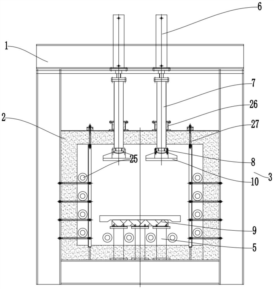
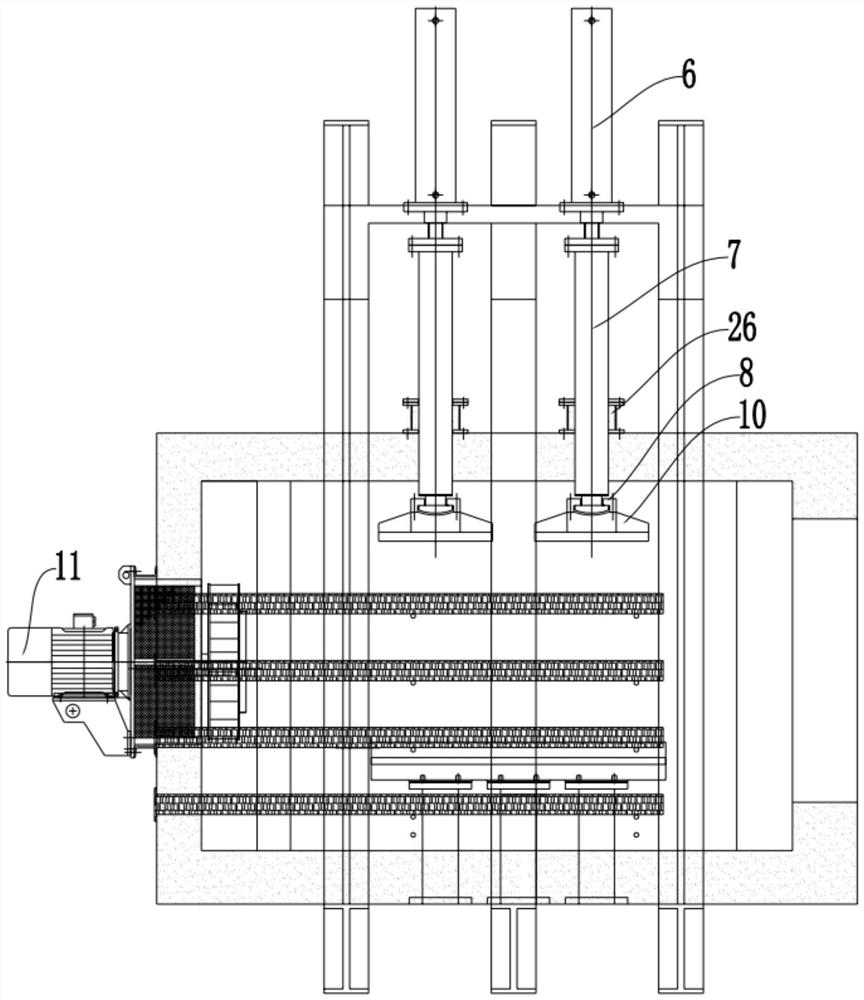
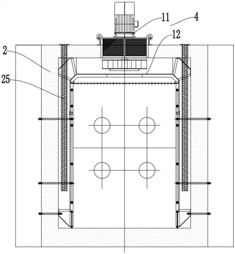
[0026] Such as Figure 1-8 As shown, the present invention is a tempering furnace air duct that is convenient for maintenance and repair, including an outer support frame 1, an inner cover 2, a pressurizing assembly 3 and a heating cycle assembly 4, and the inner cover 2 is arranged inside the outer support frame 1, The lower end of the pressurizing assembly 3 and the heating circulation assembly 4 are both arranged inside the inner cover 2, and...


PUM


Abstract

The tempering furnace air duct convenient to maintain and repair comprises an outer supporting frame, an inner cover, a pressurizing assembly and a heating circulation assembly, the inner cover is arranged in the outer supporting frame, the lower end of the pressurizing assembly and the heating circulation assembly are both arranged in the inner cover, and the heating circulation assembly is arranged on the outer side of the pressurizing assembly in a sleeving mode; the pressurizing assembly comprises a lower pressing rod, an oil cylinder, an upper pressing rod and a bearing bush, the lower pressing rod is arranged at the inner bottom of the inner cover, a lower pressing disc is arranged at the upper end of the lower pressing rod, the oil cylinder is arranged at the upper end of the outer supporting frame, the lower pressing rod is arranged at the telescopic end of the oil cylinder, and the lower end of the lower pressing rod penetrates through the upper end of the inner cover and is arranged in the inner cover; the lower end of the lower pressing rod is connected with an upper pressing disc. The invention belongs to the technical field of tempering furnace air ducts, and particularly provides a tempering furnace air duct convenient to maintain and repair. The tempering furnace air duct convenient to maintain and repair is simple in structure, high in workpiece tempering stability, high in tempering efficiency, convenient to maintain and low in maintenance difficulty.

Description

technical field [0001] The invention belongs to the technical field of tempering furnace air ducts, in particular to a tempering furnace air duct which is convenient for maintenance and repair. Background technique [0002] The use of tempering furnaces is very common now, but one of the most common disadvantages in the use of tempering furnaces is that the setting of the air inlet of the tempering furnace is relatively simple, and the air duct is directly into the furnace body, which leads to the concentration of the wind coming out of the air duct. The wind can hardly blow to the peripheral parts of the tempering furnace, which makes it difficult to control the temperature of the tempering furnace, which is not conducive to the use of the tempering furnace. [0003] When the existing tempering furnace air duct is in use, due to the strong wind force, the stability of the workpiece cannot be guaranteed, and the wind force is not uniform, resulting in reduced tempering effic...

Claims


Application Information

Patent Timeline
Patent Type & Authority Applications(China)
IPC IPC(8): C21D9/00
Inventor 韩涛朱德智张现伟
Owner SHANDONG HEIXUANFENG SAW IND
Why Eureka
Try Eureka