Y-shaped sedimentation type flow guide pier suitable for combination of gate station

A subsidence, diversion pier technology, applied in pumping stations, water conservancy projects, marine engineering, etc., can solve the decline of pump energy performance and cavitation performance, social and economic benefits discounts, and the complexity of upstream and downstream flow patterns of the hub, etc. problems, to achieve the effect of improving water inflow, reducing sedimentation, great economic value and social benefits

Active Publication Date: 2022-04-08
YANGZHOU UNIV
View PDF9 Cites 2 Cited by
  • Summary
  • Abstract
  • Description
  • Claims
  • Application Information

AI Technical Summary

Problems solved by technology

[0003] However, due to the structural limitations of the gate station combined with the project itself, it is more likely to cause the complexity of the flow regime upstream and downstream of the hub compared to the case of separate construction of the gate and pump station
When the sluice and the pump station operate independently, because the flow direction of the water flow forms an angle with the river bed, backflow and oblique flow are easy to occur upstream and downstream of the sluice station hub, which leads to the complexity of the influent flow pattern
Bad flow patterns such as backflow and oblique flow in the upstream and downstream of the hub will seriously affect the flow pattern in the water inlet channel of the pump station, changing the flow direction of the water entering the pump, resulting in a decrease in the energy performance and cavitation performance of the pump
At the same time, due to the existence of the pump station, the effective water passage width of the sluice hole will be reduced, resulting in a decrease in the flow capacity of the sluice
[0004] If these problems cannot be effectively resolved, the social and economic benefits of the gate station integration project will be greatly reduced

Method used


Image

  • Y-shaped sedimentation type flow guide pier suitable for combination of gate station
  • Y-shaped sedimentation type flow guide pier suitable for combination of gate station
  • Y-shaped sedimentation type flow guide pier suitable for combination of gate station

Examples


Embodiment Construction

[0037] The present invention will be further explained below in conjunction with the accompanying drawings.

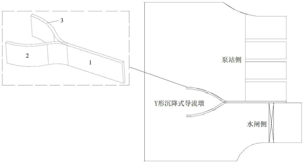
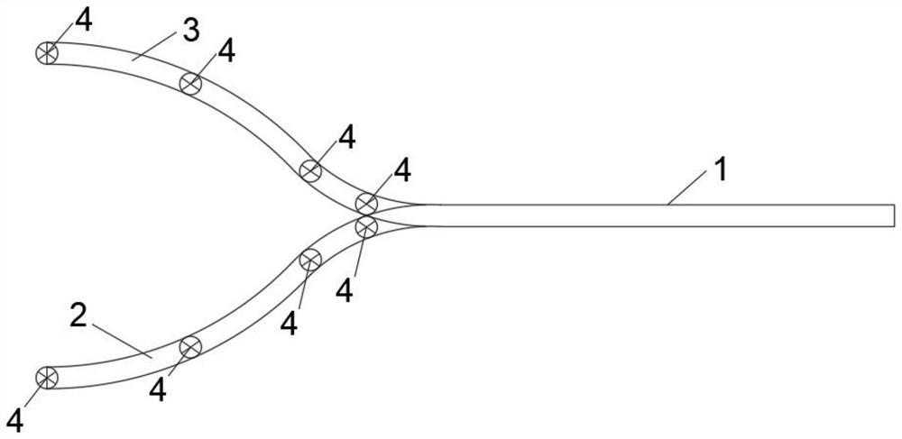
[0038] Such as figure 1 , figure 2 As shown, a Y-shaped subsidence type diversion pier suitable for the combination of gate and station includes a long straight body section 1, a first arc body section 2 and a second arc body section 3, the first arc body section 2 and The second arc body segment 3 is arranged oppositely and spliced ​​with the long straight body segment 1 to form a Y-shaped structure. The Y-shaped subsidence diversion pier is arranged at the junction of the sluice and the pump station in the combination of the sluice station. The long straight section 1 is connected with the pier at the junction of the sluice and the pump station, and the long straight section 1 is connected with the forebay of the pump station and the pier of the pump station. The foundation floor of the sluice is poured as a whole; the first arc body section 2 is located on the si...


PUM


Abstract

The Y-shaped sedimentation type flow guide pier comprises a long straight body section, a first arc body section and a second arc body section, and the first arc body section and the second arc body section are oppositely arranged and spliced with the long straight body section to form a Y-shaped structure; the Y-shaped sedimentation type flow guide mop is arranged at the joint of a water gate and a pump station in gate-station combination, the long straight body section is connected with a gate pier at the joint of the water gate and the pump station, the first arc body section is located on the side of the water gate, and the second arc body section is located on the side of the pump station. The first arc body section and the second arc body section are respectively supported by a hydraulic lifting platform at the bottom, the pump station independently operates by controlling the hydraulic lifting platform to enable the second arc body section to sink below the water gate and the pump station foundation, and when the water gate independently operates, the hydraulic lifting platform is controlled to enable the first arc body section to sink below the water gate and the pump station foundation. According to the Y-shaped sedimentation type flow guide pier, by isolating backflow, the water inlet condition of the side wall is optimized, and then the water inlet condition of a gate station combination project is improved.

Description

technical field [0001] The invention relates to a Y-shaped subsidence type diversion pier. Background technique [0002] Sluice gates and pump stations are two common hydraulic structures in water conservancy projects. Through the opening and closing of sluice gates, various functions such as tidal protection, flood discharge, and waterlogging can be realized. When there is a requirement for water diversion or water transfer, the sluice gate is closed, and the water pump is used to pump water from the side with a lower water level to the other side. Therefore, the pumping station and the sluice are often arranged in conjunction to achieve complementary functions. In addition, the combination project of the gate station is compactly arranged, and the foundation of the pump station and the sluice are connected together. The cofferdam project required for construction is small and the construction period is short. Therefore, the pumping station combined with the gate station h...

Claims


Application Information

Patent Timeline
Patent Type & Authority Applications(China)
IPC IPC(8): E02B7/20E03B5/00E02B8/06
CPCY02E10/20
Inventor 徐波刘健峰陆伟刚陆林广徐磊
Owner YANGZHOU UNIV
Why Eureka
Try Eureka