
Intelligent and rapid shield tail sealing device

A shield tail sealing and fast technology, applied in the field of shield machines, can solve the problems of easy leakage of the shield tail, high wear rate of the tail brush, and increasing the amount of grease on the shield tail.

Active Publication Date: 2022-04-08
NINGBO ELECTRIC POWER DESIGN INST
View PDF7 Cites 0 Cited by
  • Summary
  • Abstract
  • Description
  • Claims
  • Application Information

AI Technical Summary

Problems solved by technology

However, due to the high wear rate of the tail brush, the shield tail is extremely easy to leak. In order to make up for this defect, there are two traditional methods. The first is to increase the amount of shield tail grease, and use grease to fill the gaps in the segments and the shield tail compartment , resulting in a substantial increase in the amount of grease per ring, and this method cannot ensure the sealing effect of the shield tail; the second is to replace the shield tail brush, because the traditional shield tail brush is connected to the inner wall of the shield tail shell by welding, so disassembly has been completed It takes a lot of manpower and material resources to damage the shield tail brush and weld the shield tail brush
Moreover, under high water pressure conditions, due to the large number of water gushing channels behind the segments, groundwater can easily seep into the tunnel, and the slurry passing through the shield tail gap can easily lock the shield body, making it impossible for the shield machine to resume tunneling.
Therefore, the traditional method of replacing the shield tail brush is extremely risky to the project

Method used


Image

  • Intelligent and rapid shield tail sealing device
  • Intelligent and rapid shield tail sealing device
  • Intelligent and rapid shield tail sealing device

Examples


Embodiment Construction

[0030] The following are specific embodiments of the present invention and in conjunction with the accompanying drawings, the technical solutions of the present invention are further described, but the present invention is not limited to these embodiments.

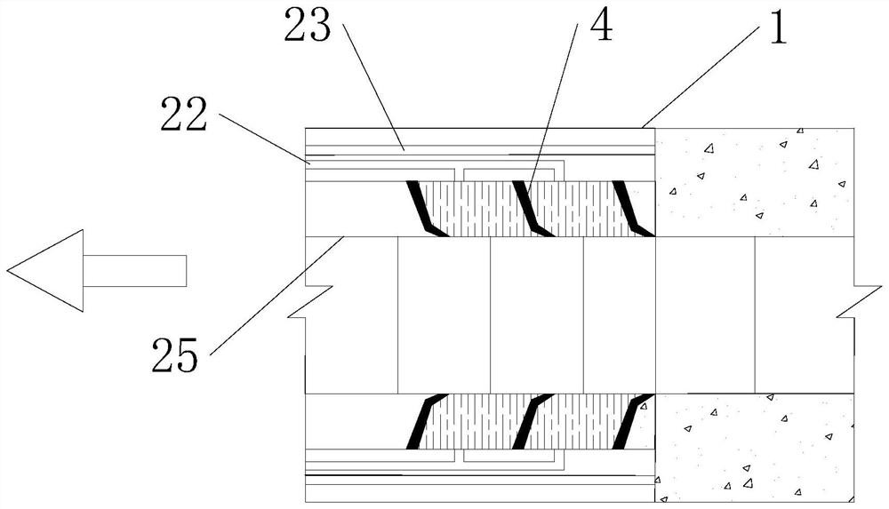
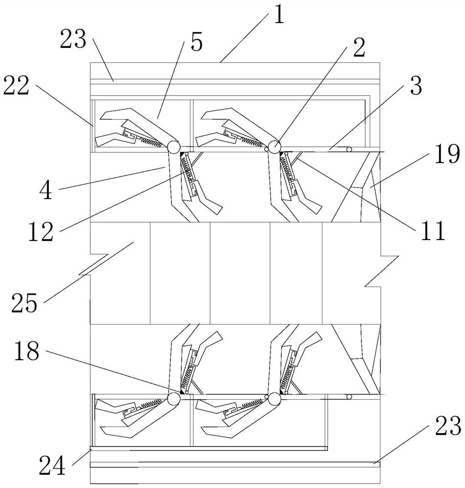
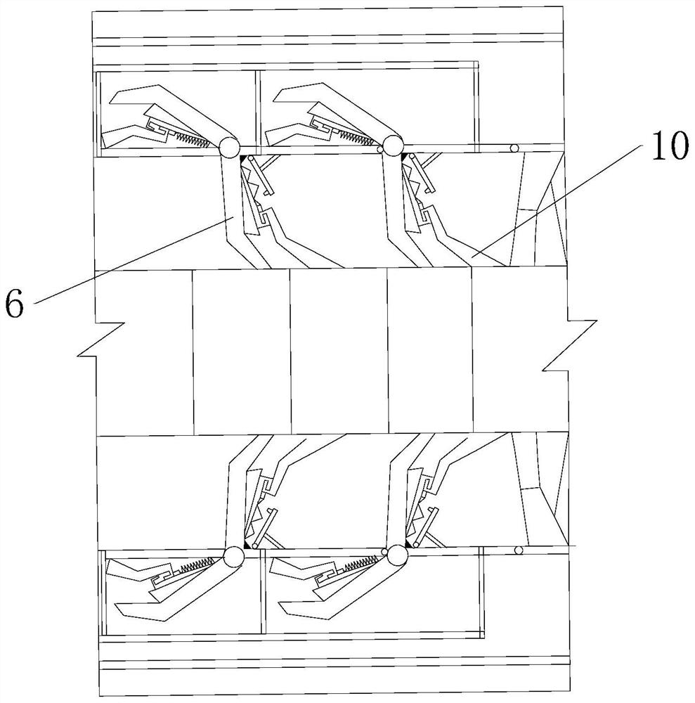
[0031] Such as figure 1 , figure 2 As shown, a kind of intelligent fast shield tail sealing device of the present invention comprises: shield tail shell 1, shield tail brush is arranged on the inner wall of shield tail shell 1, shield tail brush is combined with segment 25, shield tail brush, shield tail The shield tail compartment is formed between the tail shell 1 inner wall and the segment 25. The shield tail shell 1 is provided with a grease injection pipe 22, a slurry injection pipe 23 and a grease collection pipe 24. The grease injection pipe 22 is a kind of hose, which injects grease into each shield tail compartment, and continuously pumps the grease to brush the shield tail. The overflow in the cavity prevents ...


PUM


Abstract

The invention belongs to the technical field of shield tunneling machines, and provides an intelligent and rapid shield tail sealing device which comprises a shield tail shell, a plurality of circles of connecting pipes are arranged on the wall face, facing a pipe piece, of the shield tail shell in the axial direction, a plurality of rotatable door plates arranged along the circumferential upper line of the shield tail shell are arranged between the connecting pipes, and the free ends of the rotatable door plates are connected with the connecting pipes; the other end of the rotatable door plate is hinged to the inner wall of the shield tail shell, a plurality of shield tail brush assemblies are rotationally connected to each connecting pipe in the circumferential direction, each shield tail brush assembly comprises a shield tail brush combination body and a standby brush combination body, and the shield tail brush combination bodies are located between the outer side of the inner wall of the shield tail shell and the duct piece; the standby brush combination body is located in an inner interlayer of the shield tail shell, and the rotatable door plate is used for replacement between the shield tail brush combination body and the standby brush combination body. Compared with the prior art, the shield tail brush has the advantages that the shield tail brush can be conveniently, simply and repeatedly replaced, and the use efficiency of the shield tunneling machine is improved.

Description

technical field [0001] The invention belongs to the technical field of shield machines, and in particular relates to an intelligent and fast shield tail sealing device. Background technique [0002] In recent years, the development and utilization of urban underground space has become one of the trends in urban infrastructure construction. The shield method has become the most commonly used construction method for urban subways, drainage, water diversion, and power tunnels due to its advantages of safety, high efficiency, and little impact on above-ground buildings. construction method. [0003] There is a tail brush at the rear of the shield machine, and the tail brush, the inner wall of the shield machine and the segments constitute the tail compartment of the shield, and a certain amount of grease filler is injected into the tail compartment of the shield to create a gap between the inner wall of the shield machine and the segments. It has a sealing effect to prevent gro...

Claims


Application Information

Patent Timeline
Patent Type & Authority Applications(China)
IPC IPC(8): E21D9/06E21D11/08
Inventor 钟维军舒恺朱剑锋姚艳周勋甜罗玉鶴白文博张舜元戴戎楠陈玄俊杨浩
Owner NINGBO ELECTRIC POWER DESIGN INST
Learn More