Vertical object self-balancing system and method, storage medium and control device
A self-balancing, object-based technology, applied in the field of control, can solve problems such as the error of the balance state of vertical objects, achieve the effects of improving service life, reducing machine loss, and solving vertical object tilting
- Summary
- Abstract
- Description
- Claims
- Application Information
AI Technical Summary
Problems solved by technology
Method used
Image

Examples
Embodiment 1
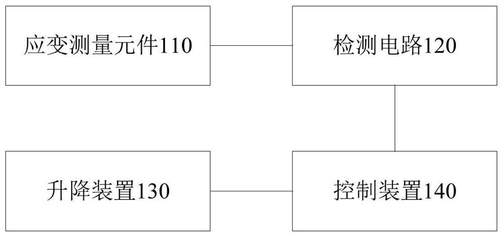
[0045] figure 1 A schematic structural diagram of a self-balancing system for a vertical object is shown, such as figure 1 As shown, the present embodiment provides a vertical object self-balancing system, comprising:
[0046] A plurality of strain measuring elements 110 are arranged at a plurality of positions on the bottom surface of the vertical object;
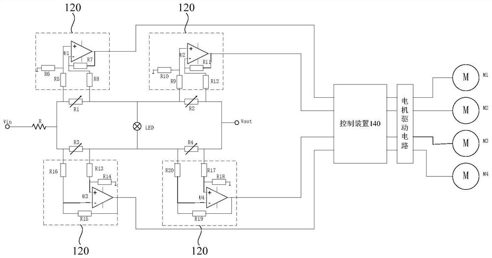
[0047] A plurality of detection circuits 120 correspond to a plurality of strain measurement elements one by one, and each detection circuit is connected to both ends of the corresponding strain measurement element for detecting the voltage value of the strain measurement element;
[0048] The lifting device 130 is arranged on the bottom surface of the vertical object, and is used to adjust the vertical object to a balanced state;
[0049] The control device 140 is connected with multiple detection circuits 1200 and the lifting device 130, and is used to obtain the voltage values detected by the multiple detection circ...
Embodiment 2
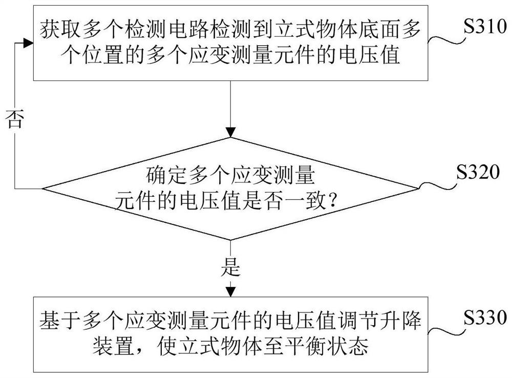
[0080] image 3 A flow chart of a self-balancing method for a vertical object is shown, as image 3 As shown, this embodiment provides a vertical object self-balancing method, which is implemented based on the vertical object self-balancing system in Embodiment 1. This method includes steps S310 to S330:
[0081] Step S310, acquiring voltage values of multiple strain measuring elements detected by multiple detection circuits at multiple positions on the bottom surface of the vertical object;
[0082] Step S320, determine whether the voltage values of the multiple strain measuring elements are consistent; in response to the inconsistent voltage values of the multiple strain measuring elements, execute step S330;
[0083] Step S330 , adjusting the lifting device based on the voltage values of the plurality of strain measuring elements, so as to bring the vertical object to a balanced state.
[0084] In some embodiments, step S330 adjusts the lifting device based on the...
Embodiment 3
[0092] This embodiment provides a storage medium, on which a computer program is stored, and when the computer program is executed by one or more processors, the method in the second embodiment is implemented.
[0093] In this embodiment, the storage medium can be realized by any type of volatile or non-volatile storage device or their combination, such as Static Random Access Memory (Static Random Access Memory, SRAM for short), Electrically Erasable and Programmable Electrically Erasable Programmable Read-Only Memory (EEPROM for short), Erasable Programmable Read-Only Memory (EPROM for short), Programmable Read-Only Memory (PROM for short) ), read-only memory (Read-Only Memory, ROM for short), magnetic memory, flash memory, magnetic disk or optical disk. For the details of the method, see Embodiment 2, which will not be repeated this time.
PUM
 Abstract
Description
Claims
Application Information
PatSnap Eureka turns technology decisions into work you can execute. Powered by our Innovation Knowledge Graph, it runs expert workflows across engineering, life sciences, materials and intellectual property. Get your review-ready output in minutes.


