
Novel laser beam repairing machine workbench

A laser beam and workbench technology, applied in laser welding equipment, manufacturing tools, metal processing equipment, etc., can solve problems such as chip yield reduction, integrated circuit opening, short circuit abnormality, etc., and achieve simple and convenient operation, clear display images, The effect of improving precision

Pending Publication Date: 2022-04-12
WUXI ZHONGWEI MASK ELECTRONICS
View PDF0 Cites 0 Cited by
  • Summary
  • Abstract
  • Description
  • Claims
  • Application Information

AI Technical Summary

Problems solved by technology

[0002] The mask is an integrated circuit design pattern composed of a chromium film on a quartz substrate. Its purpose is to transfer the designed integrated circuit pattern to the wafer using mask projection. Repairing is an important process, especially when the integrated circuit process develops to the 7nm technology node, as the feature size of the graphics becomes smaller and the graphics are complex and diverse, the requirements for defects become more and more stringent. In photolithography and other process processes, defects are re-engraved on the wafer, which eventually leads to abnormal opening and short circuit of the integrated circuit, which reduces the yield rate of the chip. If it is not repaired, it will be scrapped, which will not only increase the production cost, but also affect the product delivery time

Method used


Image

  • Novel laser beam repairing machine workbench
  • Novel laser beam repairing machine workbench

Examples


Embodiment 1

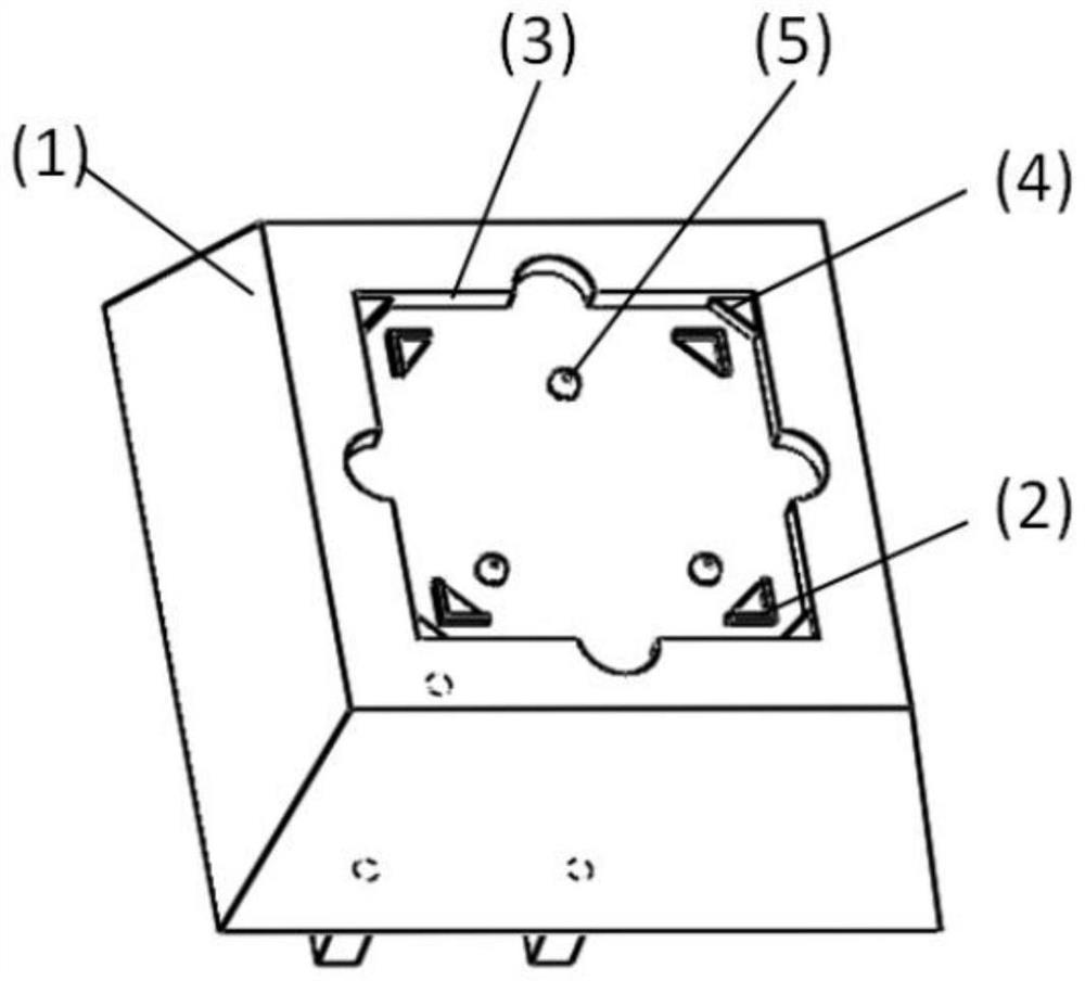
[0014] Such as figure 1 As shown, the specific embodiment adopts the following technical solutions: a novel laser beam repair machine workbench, including a placement platform 1, the top of the placement platform 1 is provided with a placement groove 3, and the four corners of the placement groove 3 are fixedly connected with triangular support plates 4. Four L-shaped limit bars 2 are fixedly connected to the bottom of the placement slot 3;

[0015] A 5-inch reticle that needs to be repaired can be placed between the L-shaped limit bars 2, and a 6-inch reticle that needs to be repaired can be placed on the triangular support plate 4 inside the placement slot 3 to achieve the purpose of flexible repair of the workbench. When taking out and replacing the mask plate, the mask plate can be grasped from the hollow grooves around it, which is convenient for operation and avoids the need to pry to take the material.

Embodiment 2

[0017] Such as figure 2 As shown, this embodiment adopts the following technical solutions:

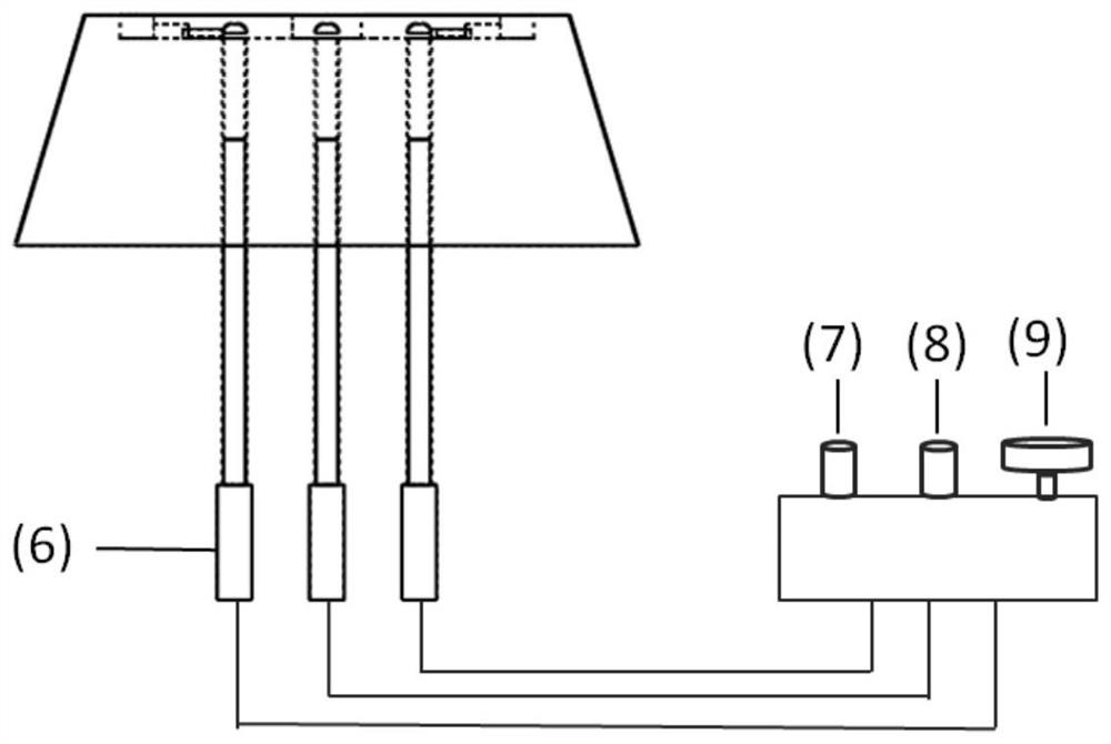
[0018] The bottom of the placement slot 3 is located between the four L-shaped limit bars 2, and three support thimbles 5 are provided. The outside of the placement slot 3 is hollowed out, and the bottom of the placement platform 1 is provided with three servo motors 6. The output end of the servo motor 6 is connected to the support The thimble 5 is threaded, and the outside of the platform 1 is provided with a controller. The controller is provided with a No. 1 toggle switch 7, a No. 2 toggle switch 8 and a fine-tuning knob 9. The controller is electrically connected with three servo motors 6 .

[0019] The servo motor 6 at the bottom of the placement platform 1 is controlled by the controller, and the three supporting thimbles 5 are simultaneously driven to rise to the initial height set by the No. 1 toggle switch 7 at the same speed, and the reticle of the repair product is comple...


PUM


Abstract

The invention discloses a novel laser beam repairing machine workbench which comprises a placing platform, a placing groove is formed in the top of the placing platform, triangular supporting plates are fixedly connected to the four corners of the placing groove, four L-shaped limiting strips are fixedly connected to the bottom of the placing groove, and three supporting ejector pins are arranged at the positions, located among the four L-shaped limiting strips, of the bottom of the placing groove. The device has the beneficial effects that the device is simple and convenient to operate, different models of masks can be limited through the placement groove and the L-shaped limiting strip, and then the masks are finely adjusted through the servo motor arranged at the bottom, so that a displayed image is clearer, and the accuracy is improved.

Description

Technical field: [0001] The invention belongs to the technical field of mask plate making, in particular to a novel laser beam repair machine workbench. Background technique: [0002] The mask is an integrated circuit design pattern composed of a chromium film on a quartz substrate. Its purpose is to transfer the designed integrated circuit pattern to the wafer using mask projection. Repairing is an important process, especially when the integrated circuit process develops to the 7nm technology node, as the feature size of the graphics becomes smaller and the graphics are complex and diverse, the requirements for defects become more and more stringent. Processes such as photolithography process will cause defects to be engraved on the wafer, which will eventually cause abnormal opening and short circuit of the integrated circuit, which will reduce the yield rate of the chip. If it is not repaired, it will be scrapped, which will not only increase the production cost, but als...

Claims


Application Information

Patent Timeline
IPC IPC(8): B23K26/70B23K26/00
Inventor 华卫群尤春刘维维薛文卿
Owner WUXI ZHONGWEI MASK ELECTRONICS
Learn More