Light low-pressure grouting equipment for rapid grouting reinforcement of tunnel

A grouting reinforcement and lightweight technology, which is applied in tunnels, tunnel linings, mining equipment, etc., can solve problems such as poor adaptability, slurry removal, and inability to grind slurry, so as to improve the grinding effect, improve the transmission efficiency, and save labor. Effect

Active Publication Date: 2022-04-12
南京康泰建筑灌浆科技有限公司
View PDF9 Cites 0 Cited by
  • Summary
  • Abstract
  • Description
  • Claims
  • Application Information

AI Technical Summary

Problems solved by technology

[0003] The Chinese utility model patent with the publication number CN210659371U discloses a cement grouting machine. The above-mentioned patent improves the stability of the cement grouting machine during operation through the motor block and the external transmission assembly, which is convenient for protecting the internal parts of the support assembly; the polyethylene The PTFE layer and the O-ring seal can prevent the pump head from jamming during long-term movement; at the same time, it can compensate for the gap caused by long-term movement and prolong the service life of the pump head; however, for the grinding treatment of the slurry and how to quickly adjust the injection The size of the pulp output of the pulp machine does not involve
[0004] The above-mentioned prior art specifically has the following problems: 1. The general grouting machine cannot remove the residual slurry in the grouting machine in time, so the grout inside the grouting machine will form residue after solidification, which will easily affect the delivery of the grouting machine efficiency
[0005] 2. During the grouting process, the traditional grouting machine only pours the slurry on the job site, but cannot grind the slurry, so the slurry mixed with particles will affect its use effect, and the existing grouting The machine cannot adjust the amount of grout according to different grouting occasions, so the adaptability is poor

Method used


Image

  • Light low-pressure grouting equipment for rapid grouting reinforcement of tunnel
  • Light low-pressure grouting equipment for rapid grouting reinforcement of tunnel
  • Light low-pressure grouting equipment for rapid grouting reinforcement of tunnel

Examples


Embodiment Construction

[0033] The embodiments of the present invention will be described in detail below with reference to the accompanying drawings, but the present invention can be implemented in many different ways defined and covered by the claims.

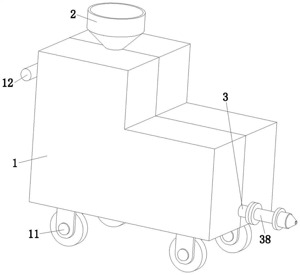
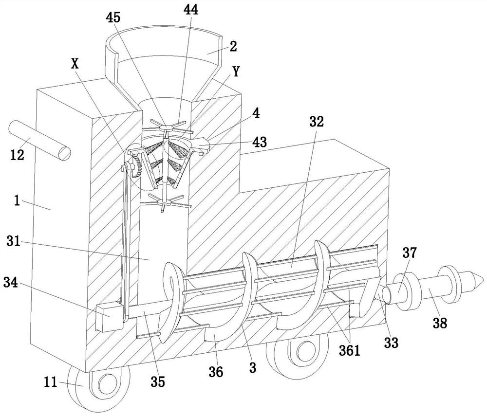
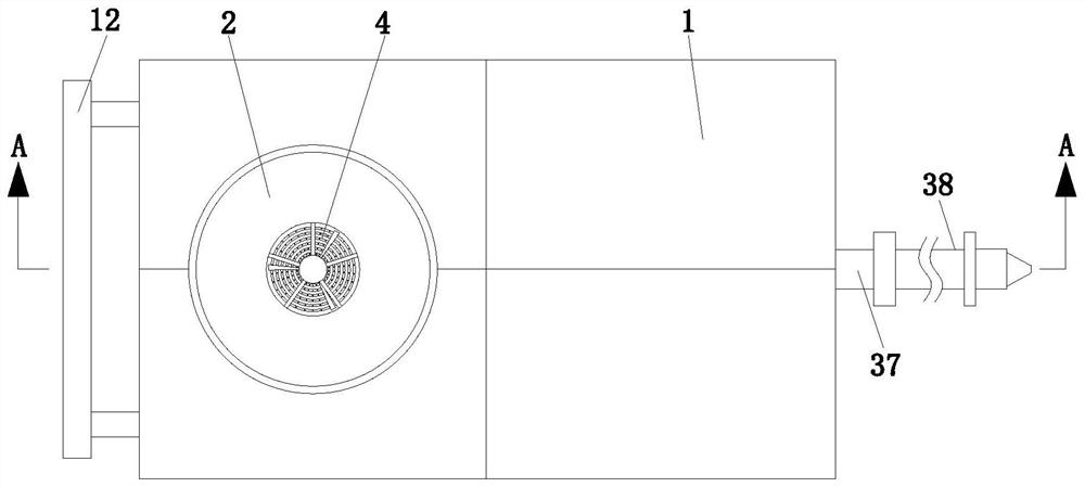
[0034] refer to figure 1 , figure 2 with image 3, a light-duty low-pressure grouting equipment for tunnel rapid grouting reinforcement, including a frame 1, a hopper 2, a conveying unit 3 and a grinding unit 4, the lower end of the frame 1 is provided with a plurality of universal wheels 11, and a plurality of universal wheels The direction wheels 11 are arranged in a matrix, and the upper side of the left end of the frame 1 is symmetrically arranged with two support rods front and back, and a hand-held rod 12 is installed on the side of the support rod away from the frame 1; During use, it is convenient for the worker to push the frame 1 to a designated position through the hand-held rod 12 and the universal wheel 11, thereby saving the labor o...


PUM


Abstract

The invention relates to the technical field of tunnel reinforcement, in particular to light low-pressure grouting equipment for tunnel rapid grouting reinforcement, which comprises a rack, a hopper, a conveying unit and a grinding unit, the hopper is arranged at the upper end of the rack, the conveying unit and the grinding unit are mounted in the rack, and the grinding unit is positioned above the conveying unit; an existing grouting machine has the following problems that a common grouting machine cannot remove residual slurry in the common grouting machine in time, so that the solidified slurry can form residues, and the conveying efficiency of the grouting machine is easily influenced; a traditional grouting machine cannot grind slurry, and therefore the using effect of the slurry doped with particles can be affected. According to the invention, residual slurry in the device can be scraped in time, so that the conveying efficiency of the device is prevented from being influenced by the residues; before grouting, slurry can be subjected to multi-stage grinding treatment, and therefore the situation that the using effect of the slurry is affected due to the fact that particles are left in the slurry can be avoided.

Description

technical field [0001] The invention relates to the technical field of tunnel reinforcement, in particular to a light low-pressure grouting equipment for rapid grouting reinforcement of tunnels. Background technique [0002] Water inrush and mud inrush in the process of tunnel construction have become one of the most important engineering disasters. Therefore, in order to control the water inrush and mud inrush in the tunnel, it is necessary to strengthen the tunnel with grouting to improve the looseness of the ground. , to increase the compressive strength and adhesiveness of the top and side of the tunnel to achieve the purpose of reinforcement, so as to avoid the adverse phenomena of water inrush and mud inrush in the tunnel. [0003] The Chinese utility model patent with the publication number CN210659371U discloses a cement grouting machine. The above-mentioned patent improves the stability of the cement grouting machine during operation through the motor block and the ...

Claims


Application Information

Patent Timeline
Patent Type & Authority Applications(China)
IPC IPC(8): B28C5/16B28C7/16B28C9/04E21D11/10
Inventor 郭建强陈森森唐和青朱海斌刘天飞杨文虎王建兴张转转何锦仪唐英波刘军华刘蔚张逸飞张劲峰李俊川王军
Owner 南京康泰建筑灌浆科技有限公司
Why Eureka
Try Eureka