Cable traction device with traction cable adjusting function for electric power engineering

A technology for electric power engineering and cable traction. It is used in transportation and packaging, transportation of filamentous materials, and thin material handling. It can solve problems such as slippage, inability to change the traction direction, and poor cable clamping effect.

Active Publication Date: 2022-04-12
国网江苏省电力有限公司射阳县供电分公司 +1
View PDF14 Cites 9 Cited by
  • Summary
  • Abstract
  • Description
  • Claims
  • Application Information

AI Technical Summary

Problems solved by technology

[0005] In order to overcome the disadvantages of easy slipping during the belt traction process, poor clamping effect on cables of different thicknesses, and inability to change the traction direction, the technical problem to be solved is: to provide a traction cable for power engineering that can change the traction direction. Adjustable cable puller

Method used


Image

  • Cable traction device with traction cable adjusting function for electric power engineering
  • Cable traction device with traction cable adjusting function for electric power engineering
  • Cable traction device with traction cable adjusting function for electric power engineering

Examples


Embodiment 1

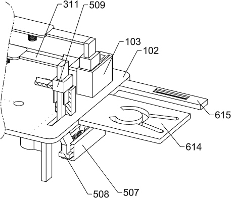
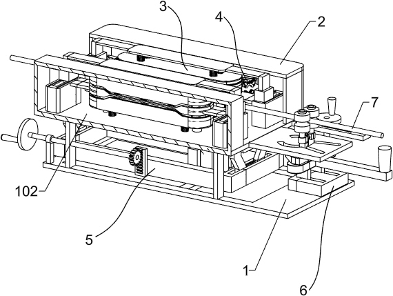
[0034] A cable pulling device with a pulling cable adjustment function for electric power engineering, such as figure 1 with figure 2 As shown, it includes a lower support plate 1, a support rod 101, an upper support plate 102, a first limit block 103, a protective shell 2, a transmission limit mechanism 3, a limit clamp mechanism 4, an auxiliary wire taking mechanism 5 and The cable guide mechanism 6, the lower support plate 1 is placed on the ground, two support rods 101 are arranged in two groups, and the two support rods 101 in one group are respectively fixedly connected to the left and right parts of the upper surface of the lower support plate 1, Two groups of support rods 101 are arranged symmetrically front and back on the upper surface of the lower support plate 1 respectively. Four first limit blocks 103 are evenly arranged on the left and right, and the lower ends of the four first limit blocks 103 are fixedly connected to the upper surface of the upper support p...

Embodiment 2

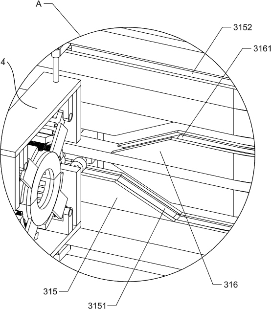
[0037] On the basis of Example 1, such as Figure 3-Figure 5 As shown, the transmission limit mechanism 3 includes a servo motor 301, a first gear 302, a second gear 303, a third gear 304, a first rotating shaft 305, a fixed rod 306, a pulley 307, a conveyor belt 308, and a second limit block 309, the third limit block 310 and the limit assembly, the lower end of the servo motor 301 is fixed on the upper surface of the lower support plate 1, the output shaft end of the servo motor 301 is fixed with the first gear 302, and the first rotating shaft 305 is connected to the upper On the right side of the support plate 102, the lower end of the first rotating shaft 305 is fixedly connected with the second gear 303 and the third gear 304. The front and rear sides of the first gear 302 mesh with the second gear 303 and the third gear 304 respectively. There are two fixed rods 306 symmetrically fixed on the front and rear sides, two first rotating shafts 305 and the upper parts of the...


PUM


Abstract

The invention relates to the field of electric power construction equipment, in particular to a cable traction device with a traction cable adjusting function for electric power engineering. The technical problems that in the belt traction process, the slipping phenomenon is prone to occurring, the clamping effect on cables with different thicknesses is poor, and the traction direction cannot be changed are solved. The invention discloses a cable traction device with a traction cable adjusting function for electric power engineering. The cable traction device comprises a transmission limiting mechanism, a limiting clamping mechanism, an auxiliary cable taking mechanism, a cable guiding mechanism and the like, the limiting clamping mechanism is arranged around the rear portion of the transmission limiting mechanism, the upper portion of the auxiliary wire taking mechanism is fixedly connected with the transmission limiting mechanism, and the cable guiding mechanism is located on the left of the auxiliary wire taking mechanism. Through cooperation of the transmission limiting mechanism and the limiting clamping mechanism, the limiting clamping mechanism adapts to the diameter of the high-voltage cable so as to clamp and convey the high-voltage cables with different diameters, and through cooperation of the auxiliary cable taking mechanism and the limiting assembly, the cable taking work of the high-voltage cable is completed.

Description

technical field [0001] The invention relates to the field of electric power construction equipment, in particular to a cable pulling device for electric power engineering with the function of adjusting the pulling cables. Background technique [0002] With the widespread use of electrical equipment, people's demand for electricity is also increasing. In some developed areas, the demand for electricity is more urgent. Therefore, the country adopts the policy of west-east power transmission to help these cities solve the problem of power shortage. During the delivery process, the high-voltage cable needs to be laid on the high-voltage wire frame. Generally, the high-voltage cable is wound on the cable drum, and the diameter of the drum can reach 3 meters. The cable drum is fixed on the cable drum frame. By pulling the cable, the high-voltage cable can be Pulled off the reel, high voltage cables can then be used for laying. [0003] At present, some traction equipment is tract...

Claims


Application Information

Patent Timeline
Patent Type & Authority Applications(China)
IPC IPC(8): B65H51/14B65H57/14
CPCY02W30/82
Inventor 邱小莲
Owner 国网江苏省电力有限公司射阳县供电分公司
Why Eureka
Try Eureka