Floating bridge structure and infrared sensing device

A sensing device, infrared technology, applied in the direction of floating bridges, bridges, bridge parts, etc., can solve the problems of small light-absorbing area of ​​the sensing unit and cumbersome process, and achieve the effect of improving process convenience, high thermal insulation effect, and high thermal insulation characteristics.

Pending Publication Date: 2022-04-12
HON HAI PRECISION IND CO LTD
View PDF0 Cites 0 Cited by
  • Summary
  • Abstract
  • Description
  • Claims
  • Application Information

AI Technical Summary

Problems solved by technology

However, the current uncooled infrared sensing devices often have the problem that the light-absorbing area of ​​the sensing unit is too small, so that the infrared sensing device needs to use more sensing units in order to have a sensitive sensing capability.
On the other hand, in order to improve the thermal insulation effect of the sensing unit, the most common method at present is to design the structure of the bridge legs as a bent structure, however, this will easily lead to an overly cumbersome process

Method used


Image

  • Floating bridge structure and infrared sensing device
  • Floating bridge structure and infrared sensing device
  • Floating bridge structure and infrared sensing device

Examples


Embodiment Construction

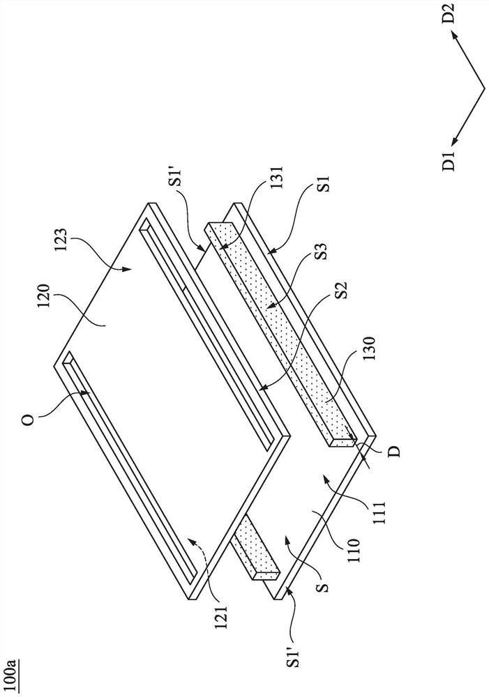
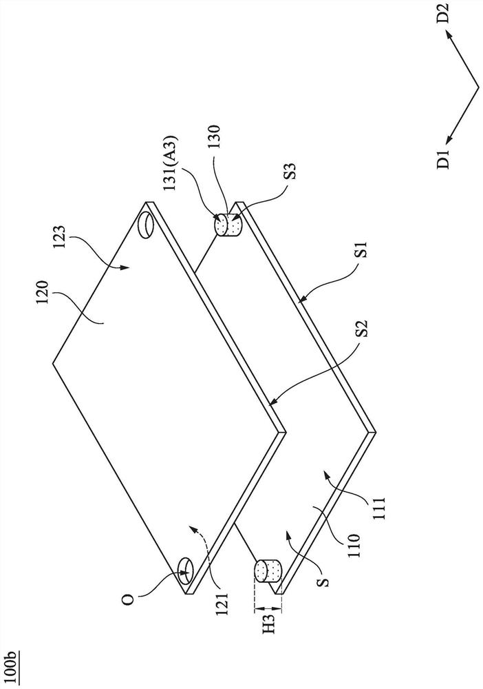
[0021] Several implementations of the present application will be disclosed below with the drawings. For the sake of clarity, many practical details will be described together in the following description. It should be understood, however, that these practical details should not be used to limit the application. That is to say, in some embodiments of the present application, these practical details are unnecessary, and thus should not be used to limit the present application. In addition, for the sake of simplifying the drawings, some existing conventional structures and elements will be shown in a simple and schematic way in the drawings. In addition, for the convenience of readers, the sizes of the elements in the drawings are not shown in actual scale.

[0022] It should be understood that although the terms "first", "second" and "third" etc. may be used herein to describe various elements, components, regions, layers and / or sections, these elements, components, regions, a...


PUM

PropertyMeasurementUnit
heightaaaaaaaaaa
heightaaaaaaaaaa
thermal conductivityaaaaaaaaaa

Abstract

A floating bridge structure comprises a substrate, a floating bridge layer and at least one bridge leg. The floating bridge layer is located on the substrate and is substantially parallel to the upper surface of the substrate. The bridge legs straightly extend from the substrate to the floating bridge layer. By means of the design, the effective light absorption area of the infrared sensing device can be increased, the overall sensing capacity of the infrared sensing device can be further improved, and the process convenience can be effectively improved.

Description

technical field [0001] The present application relates to a floating bridge structure and an infrared sensing device comprising the floating bridge structure. Background technique [0002] Generally speaking, the uncooled infrared sensing device can convert the infrared radiant heat emitted by the target into an electrical signal, so as to sense the target accordingly. However, the current uncooled infrared sensing device often has the problem that the light-absorbing area of ​​the sensing unit is too small, so that the infrared sensing device needs to use more sensing units in order to have a sensitive sensing capability. On the other hand, in order to improve the thermal insulation effect of the sensing unit, the most common method at present is to design the structure of the bridge leg as a bent structure, however, this will easily lead to a cumbersome process. Based on the above, how to increase the effective light-absorbing area of ​​a single sensing unit in an infrare...

Claims


Application Information

Patent Timeline
Patent Type & Authority Applications(China)
IPC IPC(8): E01D15/14E01D19/00G01J5/20
Inventor 庄尚余蒋光浩
Owner HON HAI PRECISION IND CO LTD
Why Eureka
Try Eureka