Signal test system

A signal test and clock signal technology, applied in the direction of measuring electricity, measuring devices, measuring electrical variables, etc., can solve the problem of signal attenuation and improvement

Pending Publication Date: 2022-04-12
LONTIUM SEMICON CORP
View PDF0 Cites 2 Cited by
  • Summary
  • Abstract
  • Description
  • Claims
  • Application Information

AI Technical Summary

Problems solved by technology

However, as the transmission rate of the signal increases, the attenuation of the signal during transmission will also increase accordingly.

Method used


Image

  • Signal test system
  • Signal test system
  • Signal test system

Examples


Embodiment Construction

[0028] In order to make the above-mentioned purpose, features and advantages of the present application more obvious and understandable, the specific implementation manners of the present application will be described in detail below in conjunction with the accompanying drawings.

[0029] In the following description, a lot of specific details are set forth in order to fully understand the application, but the application can also be implemented in other ways different from those described here, and those skilled in the art can do it without violating the content of the application. By analogy, the present application is therefore not limited by the specific embodiments disclosed below.

[0030] Secondly, the present application is described in detail in combination with schematic diagrams. When describing the embodiments of the present application in detail, for the convenience of explanation, the cross-sectional view showing the device structure will not be partially enlarged...


PUM


Abstract

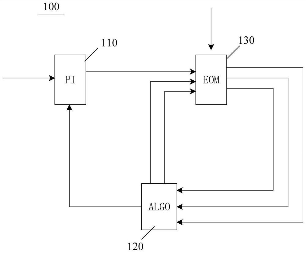
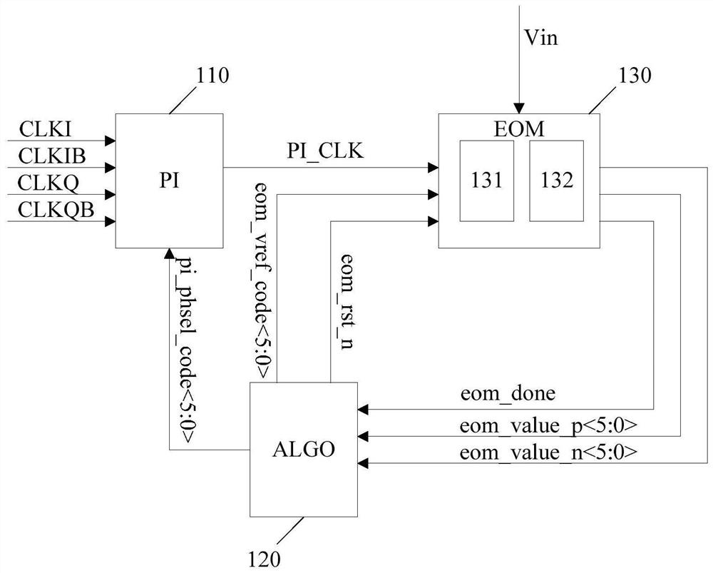
The invention provides a signal testing system which comprises a PI module, an ALGO module and an EOM module, the PI module is used for receiving a plurality of initial clock signals which are orthogonal in pairs and a clock phase control signal sent by the ALGO module and outputting a target clock signal, and the EOM module is used for receiving a to-be-tested signal, the target clock signal and a threshold voltage control signal sent by the ALGO module and outputting the target clock signal. The EOM module is used for outputting a statistical result of sampling a to-be-detected signal, the ALGO module is used for receiving the statistical result, determining an eye width value and an eye height value of an eye pattern of the to-be-detected signal, and sampling and counting the to-be-detected signal by using a target clock signal input by the phase interpolation PI module and a threshold voltage control signal sent by the ALGO module through the EOM module; the ALGO module determines the eye width value and the eye height value of the eye pattern of the to-be-tested signal according to the obtained statistical result, automatic storage and reading of the eye height and the eye width of the high-speed signal are achieved, and the power consumption of the signal testing system is low.

Description

technical field [0001] The invention relates to the field of signal testing, in particular to a signal testing system. Background technique [0002] With the advancement of technology, the demand for high-speed transmission of signals is increasing. However, as the transmission rate of the signal increases, the attenuation of the signal during transmission will increase accordingly. Therefore, in the system of high-speed signal transmission, equalization technology will be used to compensate the loss of high-frequency channels. Then the equalized signal can be tested to obtain the parameters of the current signal, and the equalization technology can be used to continue to optimize the signal. [0003] When testing a signal, the eye diagram can reflect the quality of the signal, and how to obtain information about the eye diagram of the signal is an urgent problem to be solved. Contents of the invention [0004] In view of this, the purpose of the present application is ...

Claims


Application Information

Patent Timeline
Patent Type & Authority Applications(China)
IPC IPC(8): G01R31/00
Inventor 卫海燕陈余季翔宇付家喜邰连梁张永领
Owner LONTIUM SEMICON CORP
Why Eureka
Try Eureka