
Control circuit of intelligent digital photo frame

A digital photo frame and control circuit technology, applied in transducer circuits, electrical components, electrical digital data processing, etc., can solve the problems that the response speed and storage space of the digital photo frame cannot meet the needs of commercial applications, and the digital photo frame cannot meet the needs, etc. , to achieve the effect of strong applicability, improved atmosphere and convenient use

Pending Publication Date: 2022-04-12
宗汉电通技术(深圳)有限公司
View PDF11 Cites 0 Cited by
  • Summary
  • Abstract
  • Description
  • Claims
  • Application Information

AI Technical Summary

Problems solved by technology

[0002] With the development of society, photos have become an indispensable part of people's daily life. The general photo frame can only hold one photo. Since the digital photo frame can load multiple photos and choose to display them on the display screen, the digital photo frame appears more and more. In more and more families, when photos are displayed in some shopping malls and parks, display screens of different sizes and resolution parameters are often required. The existing digital photo frames cannot meet the needs, and the response speed and storage space of the existing digital photo frames are also insufficient. Meet the needs of commercial applications

Method used


Image

  • Control circuit of intelligent digital photo frame
  • Control circuit of intelligent digital photo frame
  • Control circuit of intelligent digital photo frame

Examples


Embodiment 1

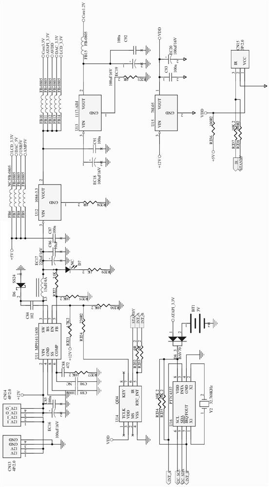
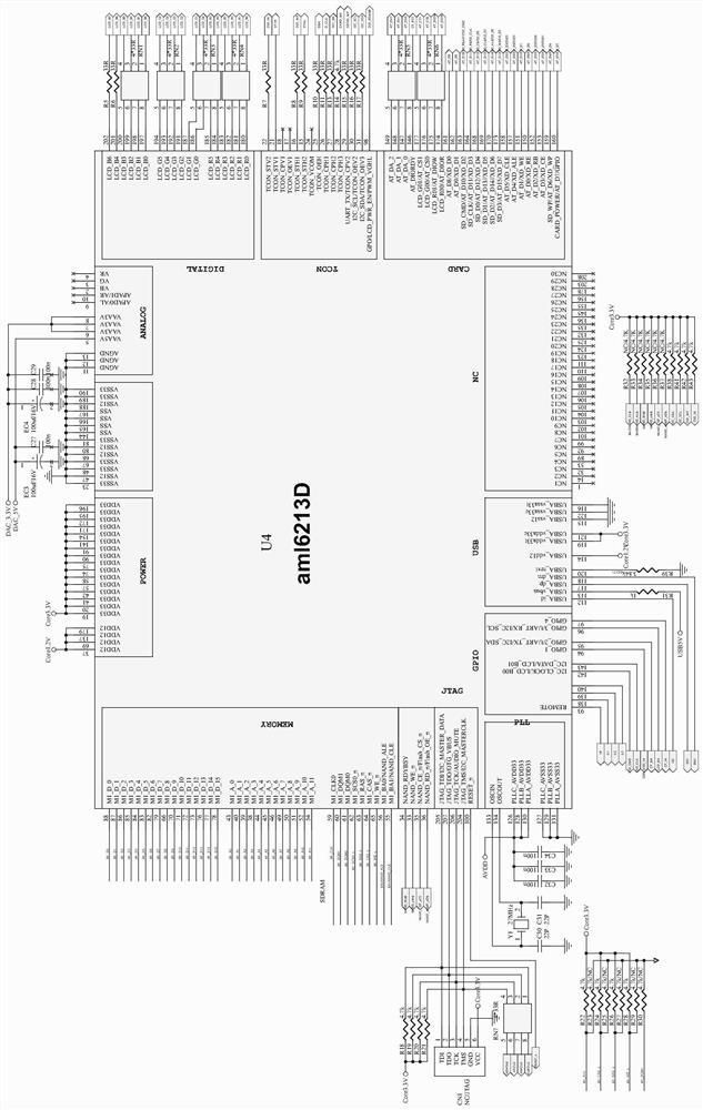
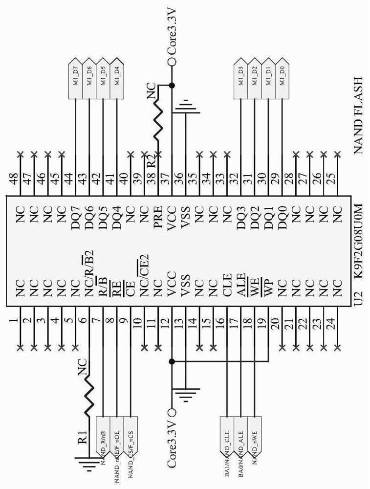
[0032] Example 1, such as Figure 1-12 As shown, a control circuit of an intelligent digital photo frame is provided, including: a power supply module, a main control module, an external storage interface module, a display interface module, an audio processing circuit and a human-computer interaction circuit, and the power supply module provides stable operation for the system voltage, the power supply module includes a power conversion circuit and a storage battery circuit, the main control module includes a chip U4, and a FLASH circuit, a flash memory circuit and a RAM circuit connected to the chip U4, and the external storage interface module is connected to the main control module Connected, including a USB interface circuit, an SD card interface circuit and a TF interface circuit, the display interface module is connected to the main control module, the display interface module includes an LCD module and a liquid crystal display module, and the LCD module includes a displa...

Embodiment 2

[0033] Example 2, such as figure 1 As shown, the power conversion circuit includes chips U11, U12 and U13, the input terminals of the chip U11 are connected to connectors CN13 and CN14, the connectors CN13 and CN14 are connected to an external 12V voltage, and the output terminal of the chip U11 outputs 5V Voltage, the input terminal of the chip U12 is connected to the output terminal of the chip U11, the output terminal outputs a 3.3V voltage, the input terminal of the chip U13 is connected to the output terminal of the chip U12, and the output terminal outputs a 1.2V voltage, the The storage battery circuit includes a chip U16, the 8 pins of the chip U16 are connected to the 3 pins of the diode BAV70, the 2 pins of the diode BAV70 are grounded through the battery BT1, the 1 pin is connected to the 3.3V voltage, the 6 and 3 pins of the chip U16 5 pins are respectively connected to pins 30 and 31 of the chip U4 via resistors R16 and R17, the model of the chip U11 is MP9141, th...

Embodiment 3

[0035] Example 3, such as figure 2 As shown, the crystal oscillator Y1 is connected between the 133 and 134 pins of the chip U4, the two ends of the crystal oscillator Y1 are grounded through the capacitors C30 and C31 respectively, and the 205, 207, 206 and 204 pins of the chip U4 are respectively connected to the interface 1, 2, 3 and 4 pins of CN1, the model of the chip U4 is aml6213D; the FLASH circuit includes a chip U2, 7, 8, 9, 18, 29, 30, 31, 32, Pins 41, 42, 43 and 44 are respectively connected to pins 34, 35, 36, 33, 88, 87, 86, 85, 84, 83, 82 and 79 of the chip U4, and the model of the chip U2 is K9F2G08U0M The flash memory circuit includes a chip U1, 9, 16, 17, 48, 1, 2, 3, 4, 5, 6, 7, 8, 18, 19, 20, 21, 22, 23, 24, 25, 45, 44, 42, 40, 38, 35, 33, 31, 29, 10, 14, 28, 11, 26 and 12 pins are respectively connected to 61, 78, 77, 76, 73, 72, 71, 70, 66, 54, 52, 51, 50, 49, 46, 45, 44, 38, 39, 40, 43, 79, 82, 83, 84, 85, 86, 87, 88, 60, 36, 33, 35 and 100 pins, the...


PUM


Abstract

The invention discloses a control circuit of an intelligent digital photo frame, which comprises a power supply module, a main control module, an external storage interface module, a display interface module, an audio processing circuit and a man-machine interaction circuit, and is characterized in that the power supply module provides stable working voltage for a system and comprises a power conversion circuit and a storage battery circuit; the main control module comprises a chip U4, and a FLASH circuit, a flash memory circuit and an RAM circuit which are connected with the chip U4, the external storage interface module is connected with the main control module and comprises a USB interface circuit, an SD card interface circuit and a TF interface circuit, the display interface module comprises an LCD module and a liquid crystal display module, the LCD module comprises a display screen booster circuit and an LCD interface circuit, and the display screen booster circuit is connected with the external storage interface module. The LCD interface circuit comprises four groups of LCD screen interfaces, and the audio processing circuit is connected with the main control module and can realize audio playing; the display device has various display modes, can be suitable for various occasions, and has good market application value.

Description

technical field [0001] The invention relates to the field of digital photo frames, in particular to a control circuit of an intelligent digital photo frame. Background technique [0002] With the development of society, photos have become an indispensable part of people's daily life. The general photo frame can only hold one photo. Since the digital photo frame can load multiple photos and choose to display them on the display screen, the digital photo frame appears more and more. In more and more families, when photos are displayed in some shopping malls and parks, display screens of different sizes and resolution parameters are often required. The existing digital photo frames cannot meet the needs, and the response speed and storage space of the existing digital photo frames are also insufficient. Meet the needs of commercial applications. Contents of the invention [0003] Aiming at the shortcomings of the existing digital photo frame, the invention provides a control...

Claims


Application Information

Patent Timeline
Patent Type & Authority Applications(China)
IPC IPC(8): G09G3/36G06F13/38H04R3/00
Inventor 吴云如刘玉凤
Owner 宗汉电通技术(深圳)有限公司
Learn More