
Cathode cable structure for impressed current cathodic protection device of thermal production well

A technology of impressed current and cathodic protection, applied in the direction of insulated cables, cables, circuits, etc., can solve problems such as high-temperature oxygen corrosion of copper or aluminum cores, potential safety hazards, aging of insulation layers, etc., to avoid corrosion damage, improve replacement efficiency, The effect of eliminating potential safety hazards

Pending Publication Date: 2022-04-12
PETROCHINA CO LTD
View PDF0 Cites 0 Cited by
  • Summary
  • Abstract
  • Description
  • Claims
  • Application Information

AI Technical Summary

Problems solved by technology

On-site cathode cables are directly welded to the outer surface of the casing. The development method of some oilfield blocks is thermal recovery. The maximum surface temperature of some casings is about 190°C. The insulation layer of the cathode cable cannot withstand such a high temperature, causing the insulation layer to age And the copper core or aluminum core is corroded by high temperature oxygen. After a period of time, the virtual connection between the cable and the bushing will generate sparks, causing safety hazards

Method used


Image

  • Cathode cable structure for impressed current cathodic protection device of thermal production well
  • Cathode cable structure for impressed current cathodic protection device of thermal production well
  • Cathode cable structure for impressed current cathodic protection device of thermal production well

Examples


Embodiment Construction

[0033] In order to understand the technical features, objects and effects of the present invention, specific embodiments of the present invention will be described with reference to the drawings.

[0034] DETAILED DESCRIPTION OF THE INVENTION The embodiments of the invention are intended to be utilized for the purposes of the present invention, without understanding of the invention. Under the teachings of the present invention, those skilled in the present invention may be considered as they belong to the scope of the invention. It should be noted that when the element is referred to as "set to" another element, it can be directly in another element or may also exist. When an element is considered to be "connected" another element, it can be directly connected to another element or may exist at the same time. The term "installation", "connected", "connection" should be broadly understood, for example, can be mechanically connected or electrically connected, or in communication in...


PUM

PropertyMeasurementUnit
Diameteraaaaaaaaaa
Lengthaaaaaaaaaa
Temperature toleranceaaaaaaaaaa

Abstract

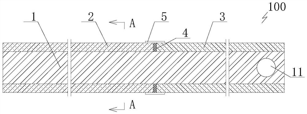
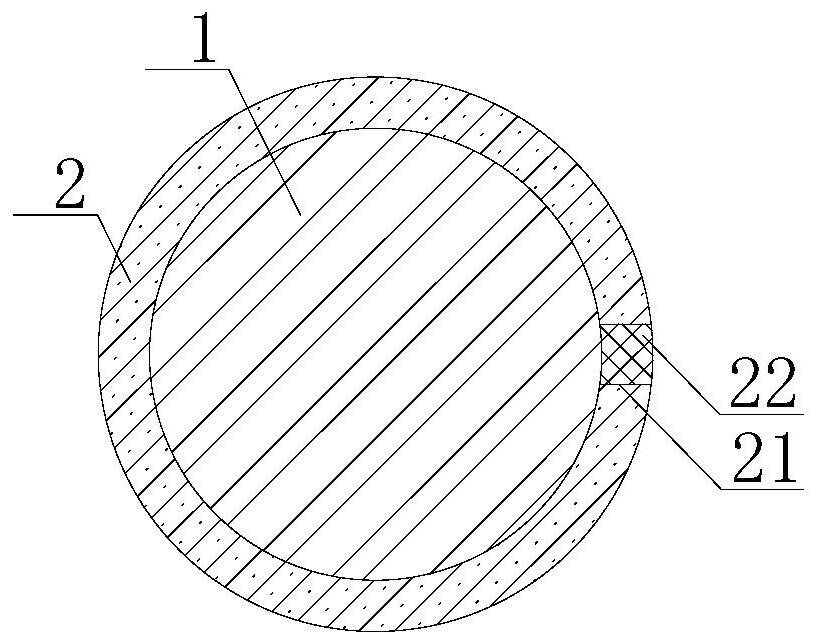
The invention relates to a cathode cable structure for an impressed current cathode protection device of a thermal production well, which comprises a stainless steel connecting section, the first end of the stainless steel connecting section can be fixedly connected to a sleeve, and the second end of the stainless steel connecting section is electrically connected with an impressed current cathode cable; a first rubber sleeve is detachably arranged on the stainless steel connecting section from the first end to the inside in a sleeving manner, and the first rubber sleeve is arranged in a high-temperature-resistant manner; the stainless steel connecting section is sleeved with a second rubber sleeve inwards from the second end, and the second rubber sleeve is oil-water resistant. The adjacent ends of the second rubber sleeve and the first rubber sleeve are arranged in an abutting mode, and the adjacent ends of the first rubber sleeve and the second rubber sleeve are in waterproof connection. A conventional cable copper core or aluminum core is replaced by the stainless steel connecting section, and the stainless steel connecting section is sleeved with the rubber sleeve for protection, so that corrosion protection can be performed on buried pipelines for oil transportation, water transportation and the like, and potential safety hazards are eliminated.

Description

Technical field [0001] The present invention relates to the field of oil production engineering, and more particularly to a cathode cable structure for thermal well-electrodeployed current cathode protection devices. Background technique [0002] At present, due to the introduction of oilfield development and production, the increasingness of the underground and ground collection pipe column corrosion is caused by the increasingness of the underground and the ground-to-hole, which causes environmental safety problems. Applying techniques for using external current cathode protection can electrochemically protect the outer surface of the downhole and the ground pipe column, one of the links in the cathode protection technology is the connection of the cathode cable and the casing, and the DC current from the power supply is overflowed to the earth. Discharge, current flows through the cathode cable to the power source through the buried line. The field cathode cable is directly we...

Claims


Application Information

Patent Timeline
IPC IPC(8): H01B7/00H01B7/17H01B7/28H01B7/29H01B7/38H01B1/02
Inventor 剪树旭郭玉强赵吉成魏凯魏秀艳张威杨忠德龚润民王鸿何妮娟杜晓雪徐雪楠许佳赛张乘铭郑君
Owner PETROCHINA CO LTD
Learn More