
Band-pass filter with adjustable center frequency

A band-pass filter, the eleventh technology, applied in the direction of frequency selection two-terminal pair network, multi-terminal pair network, etc., can solve the problems of narrow pass frequency band, high cost, and large band-pass signal attenuation

Pending Publication Date: 2022-04-12
宁波通导电子有限公司
View PDF0 Cites 0 Cited by
  • Summary
  • Abstract
  • Description
  • Claims
  • Application Information

AI Technical Summary

Problems solved by technology

[0003] There are two main types of existing band-pass filters. The first type of band-pass filter is designed with fixed parameters, its center frequency is fixed, the pass band is narrow, and the filtering effect of clutter interference signals is good, but it can only For single-band, when it is necessary to meet the needs of detection equipment such as depth sounders with frequencies ranging from 50kHz to 500kHz, when the current transmission signal uses 3 or more frequency signals, it needs to be equipped with multiple frequency bands with different center frequencies. Band-pass filter is used for switching, and the cost is high; the second type of band-pass filter is designed so that its working frequency band includes multiple frequency bands, has a wide pass band, and the center frequency is adjustable, although it can be used for With multiple frequency bands, the cost is low, but it is inevitable to introduce a large number of clutter interference signals, and the bandpass signal attenuation is relatively large, so that the filtering effect of clutter interference signals is poor.

Method used


Image

  • Band-pass filter with adjustable center frequency
  • Band-pass filter with adjustable center frequency
  • Band-pass filter with adjustable center frequency

Examples


Embodiment

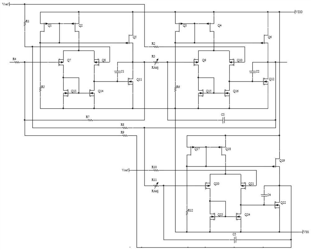
[0011] Example: such as figure 1As shown, a bandpass filter with adjustable center frequency includes a first resistor R1, a second resistor R2, a third resistor R3, a fourth resistor R4, a fifth resistor R5, a sixth resistor R6, and a seventh resistor R7 , the eighth resistor R8, the ninth resistor R9, the tenth resistor R10, the eleventh resistor R11, the twelfth resistor R12, the first capacitor C1, the second capacitor C2, the third capacitor C3, the fourth capacitor C4, the fifth Capacitor C5, first transistor Q1, second transistor Q2, third transistor Q3, fourth transistor Q4, fifth transistor Q5, sixth transistor Q6, seventh transistor Q7, eighth transistor Q8, ninth transistor Q9, tenth Transistor Q10, eleventh transistor Q11, twelfth transistor Q12, thirteenth transistor Q13, fourteenth transistor Q14, fifteenth transistor Q15, sixteenth transistor Q16, seventeenth transistor Q17, eighteenth transistor Q18 , the nineteenth transistor Q19, the twentieth transistor Q20...


PUM


Abstract

The invention discloses a band-pass filter with an adjustable center frequency. Comprising a first resistor, a second resistor, a third resistor, a fourth resistor, a fifth resistor, a sixth resistor, a seventh resistor, an eighth resistor, a ninth resistor, a tenth resistor, an eleventh resistor, a twelfth resistor, a first capacitor, a second capacitor, a third capacitor, a fourth capacitor, a fifth capacitor, a first transistor, a second transistor, a third transistor, a fourth transistor and a fifth transistor. A sixth transistor, a seventh transistor, an eighth transistor, a ninth transistor, a tenth transistor, an eleventh transistor, a twelfth transistor, a thirteenth transistor, a fourteenth transistor, a fifteenth transistor, a sixteenth transistor, a seventeenth transistor, an eighteenth transistor, a nineteenth transistor, a twentieth transistor, a twenty-first transistor and a twenty-second transistor; a twenty-third transistor and a twenty-fourth transistor; the filter has the advantages that the adjustment of the center frequency can be quickly realized, the requirement of multi-frequency-band filtering is met, the cost is low, the transmission band corresponding to each center frequency is narrow, the quality factor Q is excellent, and the clutter interference signal filtering effect is good.

Description

technical field [0001] The invention relates to a band-pass filter, in particular to a band-pass filter with adjustable center frequency. Background technique [0002] Depth sounders, fish finders and other detection systems used by ships rely on the transmission of detection signals, and by analyzing the received echo signals, calculations are made to obtain detection information. Such detection systems also have various detection radars, sonar etc. With the development of detection technology, signals of different frequencies have different properties of the reflected echoes of the same target. Analyzing signals of different frequencies will obtain more comprehensive target information, which is an inevitable trend in the development of detection system technology. . The challenge brought by different detection signal frequencies is whether the signal processing capability of the receiving circuit can quickly and accurately separate the target signal from the clutter. Th...

Claims


Application Information

Patent Timeline
Patent Type & Authority Applications(China)
IPC IPC(8): H03H11/04
Inventor 侯乔木乐瑜
Owner 宁波通导电子有限公司
Learn More