Medical lower limb and leg fatigue relieving equipment

A medical and leg technology, applied in the field of leg fatigue alleviation equipment, can solve the problems of leg fatigue alleviation and lack of a fixed mechanism, and achieve the effect of alleviating fatigue

Pending Publication Date: 2022-04-15
李明星
View PDF0 Cites 0 Cited by
  • Summary
  • Abstract
  • Description
  • Claims
  • Application Information

AI Technical Summary

Problems solved by technology

[0004] Aiming at the deficiencies in the prior art, the present invention provides a medical lower limb leg fatigue relief device that can fix the patient's legs and avoid damage to the patient's legs, so as to overcome the existing relief devices that have no fixing mechanism and cannot Disadvantages of Effective Leg Fatigue Relief

Method used


Image

  • Medical lower limb and leg fatigue relieving equipment
  • Medical lower limb and leg fatigue relieving equipment
  • Medical lower limb and leg fatigue relieving equipment

Examples


Embodiment 1

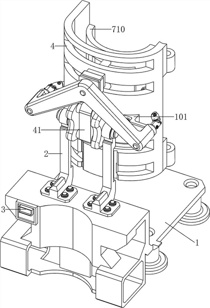
[0106] A medical device for relieving fatigue of lower limbs and legs, now refer to Figure 1-3 , including a base frame 1, a bracket 2, a supporting arc plate 4, a connecting block frame 41, a limit mechanism 5, a tilting mechanism 6, a stabilizing mechanism 7 and a cold compressing mechanism 8, and the upper front side of the base frame 1 is fixed with a bracket through bolts 2. The bracket 2 is rotatably provided with a connecting swivel frame 41, and a supporting arc plate 4 is welded on the connecting swivel frame 41. The bottom frame 1 is provided with a limit mechanism 5, and the bottom frame 1 is provided with a tilting mechanism 6. The bracket 2 A stabilizing mechanism 7 is arranged between the support arc plate 4 and a cold compress mechanism 8 is arranged on the stabilizing mechanism 7 .

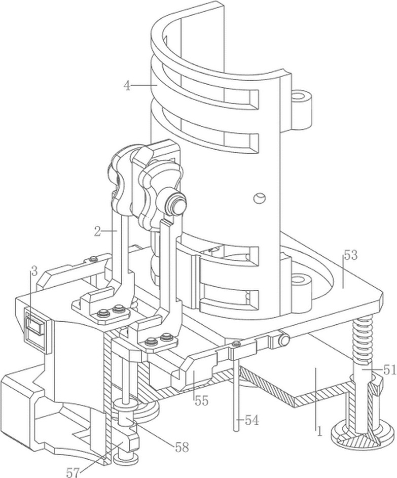
[0107] now refer to Figure 3-4 , the limit mechanism 5 includes a first telescopic rod 51, a first spring 52, a clamp 53, a guide rod 54, a connecting frame 55, a contact switch...

Embodiment 2

[0113] On the basis of embodiment 1, now refer to Figure 13-15 , also includes a massage mechanism 9, the massage mechanism 9 includes a temperature sensor 91, a first support block 92, a slide bar 93, a fourth spring 94, a guide wheel 95, a stay cord 96, a moving block 97, a second motor frame 98, Geared motor 99, winch reel 910, connection block 911 and rolling barrel 912, temperature sensor 91 is arranged on the right side of the temperature insulation plate 81 front portion on the upper side, and the left and right sides of the front portion of arc holding plate 710 are all provided with first There are four support blocks 92, the first support block 92 has four, a slide bar 93 is connected between the two first support blocks 92 on the same side, and a moving block 97 is slidably connected between the two slide bars 93, the bottom of the moving block 97 A fourth spring 94 is connected between the left and right sides and the first supporting block 92 on the same side, th...


PUM


Abstract

The invention relates to leg fatigue relieving equipment, in particular to medical lower limb and leg fatigue relieving equipment. According to the medical lower limb and leg fatigue relieving equipment, the legs of a patient can be fixed, and injury to the legs of the patient can be avoided. Medical lower limb and leg fatigue relieving equipment comprises a bottom frame, a support, a connecting rotating block frame, a limiting mechanism, an inclining mechanism, a stabilizing mechanism and the like. A support is arranged on the front side of the upper portion of the bottom frame, a connecting rotating block frame is rotatably arranged on the support, a limiting mechanism and an inclining mechanism are arranged on the bottom frame, and a stabilizing mechanism is arranged between the support and the supporting arc plate. When people place legs needing to relieve fatigue on an arc-shaped containing plate, when an arc-shaped pressing plate reversely rotates to make contact with the legs of people, the arc-shaped pressing plate adaptively moves backwards, so that a second telescopic rod is compressed, a third spring is compressed, and the effect of fixing the legs is achieved.

Description

technical field [0001] The invention relates to a leg fatigue relief device, in particular to a medical lower limb fatigue relief device. Background technique [0002] In the hospital, there are many patients with leg injuries. Patients with leg injuries generally need surgical treatment, and rehabilitation training will be carried out after the operation. Due to the long rehabilitation training time, the patient's leg muscles are relatively fragile, which leads to the recovery of the patient. The soreness and fatigue of the leg muscles after training can easily cause muscle spasms, which is not conducive to the rehabilitation of patients. At present, there are still some problems in the existing leg fatigue relief equipment: when fatigue relief is performed on the patient's legs, it cannot relieve the patient's fatigue. If the legs are effectively fixed, the patient's legs are easy to shift and not comfortable enough, and most of the leg fatigue relief equipment can only pe...

Claims


Application Information

Patent Timeline
Patent Type & Authority Applications(China)
IPC IPC(8): A61F7/00A61H15/00A61H15/02
CPCA61F7/007A61H15/0078A61H15/02A61F2007/0039A61F2007/0075A61F2007/0096A61H2015/0014A61H2201/0207A61H2201/0285A61H2201/1207A61H2201/1642A61H2201/5025A61H2201/5071A61H2201/5082A61H2201/5092A61H2205/10
Inventor 李明星
Owner 李明星
Why Eureka
Try Eureka