
Performance detection system for diaphragm compressor

A diaphragm compressor and detection system technology, applied in pump testing, mechanical equipment, machines/engines, etc., can solve problems such as unstable intake pressure and inability to detect whether the compressor meets technical requirements

Pending Publication Date: 2022-04-15
HUANENG CLEAN ENERGY RES INST +2
View PDF0 Cites 0 Cited by
  • Summary
  • Abstract
  • Description
  • Claims
  • Application Information

AI Technical Summary

Problems solved by technology

Diaphragm compressors are widely used. The performance index of this type of compressor, the discharge flow rate, is mainly affected by the intake pressure of the compressor. Therefore, the design of the discharge flow rate of the diaphragm compressor is based on the constant intake pressure. Manufacture, and also allow the intake pressure to be used within a certain range of pressure fluctuations; based on this situation, the intake pressure is often unstable during production and use, such as: After the 20MPa long tube trailer is transported to the hydrogen refueling station, the diaphragm type The compressor performs secondary pressurization to refill the fuel cell bus. The intake pressure of the compressor, that is, the pressure of the long-tube trailer, decreases with the continuous filling of the fuel cell bus. Therefore, after the installation, commissioning, and acceptance of the compressor During the process, due to site conditions or actual conditions, it is impossible to detect whether the compressor meets the technical requirements

Method used


Image

  • Performance detection system for diaphragm compressor

Examples


Embodiment Construction

[0019] Embodiments of the present application are described in detail below, examples of which are shown in the drawings, wherein the same or similar reference numerals denote the same or similar elements or elements having the same or similar functions throughout. The embodiments described below by referring to the figures are exemplary, and are only for explaining the present application, and should not be construed as limiting the present application. On the contrary, the embodiments of the present application include all changes, modifications and equivalents falling within the spirit and scope of the appended claims.

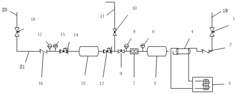
[0020] figure 1 It is a structural schematic diagram of a diaphragm compressor performance detection system proposed by an embodiment of the present application.

[0021] see figure 1 , a diaphragm compressor performance detection system, comprising an air intake pipeline 19 connected to the diaphragm compressor air outlet and an air outlet pipeline 20 co...


PUM


Abstract

The diaphragm compressor performance detection system comprises an air inlet pipeline connected to an exhaust port of a diaphragm compressor and an air outlet pipeline connected to an air inlet of the diaphragm compressor, the air inlet pipeline is provided with a first valve, and the air outlet pipeline is provided with a third valve. A detection pipeline is communicated between the air inlet pipeline and the air outlet pipeline, a pressure reduction assembly is arranged on the detection pipeline to adjust the pressure in the detection pipeline, and a flow indicating device and a pressure indicating device are further arranged on the detection pipeline to detect the pressure and the flow of the detection pipeline. Through the flow indicating device and the pressure indicating device on the detection pipeline, whether the performance indexes of the diaphragm compressor under different air inlet pressures are consistent with the design or not is monitored through the flow and the pressure of the circulation pipeline, and the blank of performance detection and acceptance of the diaphragm compressor is filled. A quicker and more scientific detection means is provided for diaphragm compressor detection, and the equipment failure rate is reduced.

Description

technical field [0001] The present application relates to the technical field of diaphragm compressors, in particular to a diaphragm compressor performance detection system. Background technique [0002] Renewable energy power generation, hydrogen and oxygen are produced through the water electrolysis hydrogen production device. The hydrogen is pressurized by the diaphragm compressor and then filled with a long-tube trailer to deliver to the hydrogen refueling station. After the long-tube trailer enters the hydrogen refueling station, it is compressed by the diaphragm. The machine is performing secondary pressurization to refuel fuel cell buses, which is a widely used hydrogen production-transportation-filling operation mode. [0003] Fuel cells are relatively strict on the quality of hydrogen, and the indicators meet high-purity hydrogen or higher requirements. The hydrogen booster basically adopts a diaphragm compressor. The advantage is that the compressed medium will not...

Claims


Application Information

Patent Timeline
IPC IPC(8): F04B51/00
Inventor 潘龙王金意张畅王鹏杰任志博余智勇徐显明王韬王凡郭海礁刘丽萍
Owner HUANENG CLEAN ENERGY RES INST
Learn More