Heat recovery system for coal mine internal combustion engine heater

An internal combustion engine heater and heat recovery technology, applied in water heaters, fluid heaters, machines/engines, etc., can solve problems such as poor heat exchange effect, heat loss, sound and air pollution, and achieve easy cleaning and replacement and reduce wear and tear , the effect of reducing noise pollution

Pending Publication Date: 2022-04-15
BEIFANG WEIJIAMAO COAL POWER CO LTD +1
View PDF7 Cites 0 Cited by
  • Summary
  • Abstract
  • Description
  • Claims
  • Application Information

AI Technical Summary

Problems solved by technology

[0002] When the internal combustion engine equipment in open-pit coal mines works in winter, it needs to heat the antifreeze around the heater through the heat generated by the heater burning diesel oil, and rely on the circulating water pump to send the antifreeze to the cab air conditioning system or the engine cylinder liner to provide the cab. Warm air, and can make the engine hot start, reduce

Method used


Image

  • Heat recovery system for coal mine internal combustion engine heater
  • Heat recovery system for coal mine internal combustion engine heater
  • Heat recovery system for coal mine internal combustion engine heater

Examples


Embodiment 1

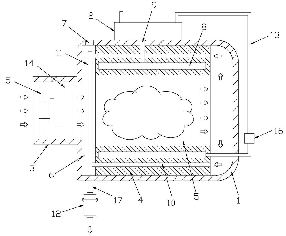
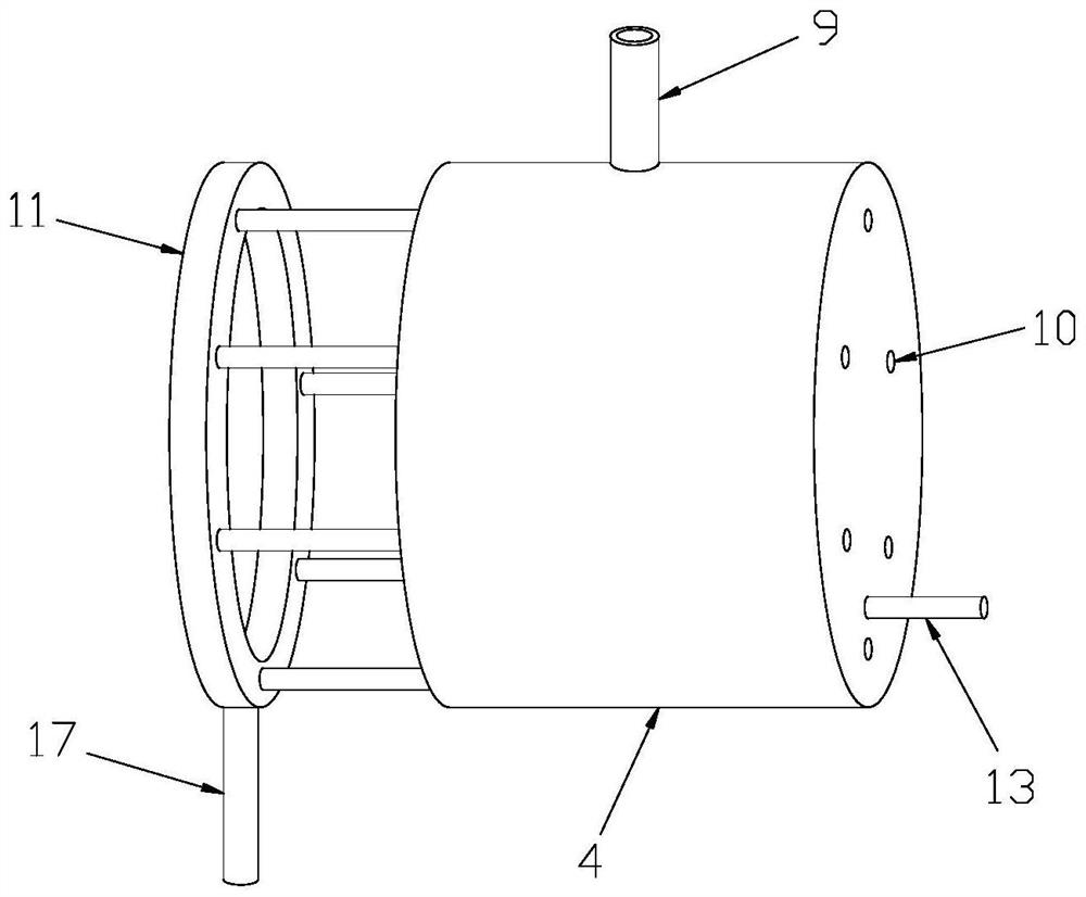
[0027] Example 1: See Figure 1-2 The present invention provides a technical solution: a heat recovery system including a coal mine, including a heater housing 1, a coolant storage case 2 located at the top of the heater housing 1 for storing a coolant; the heater The upper left end of the body 1 is provided with a vent, the air outlet 3 is attached to the mixing chamber 15, and the air can be transported to the mixing chamber 6 and the combustible product is combined after mixing by the combustion chamber 5. The inside of the heater housing 1 is provided with a steel cylinder 4, and there is a combustion chamber 5 inner, and the internal portion of the combustion chamber 5 has a silicon nitride ceramic, which can be heated to a high temperature, and the inside of the heater housing 1 is heated. The steel cylinder 4 is provided with a mixing chamber 6 on one side of the vent 3, and a combustible product is provided in the top of the heater housing 1, and the combustible material is...

Embodiment 2

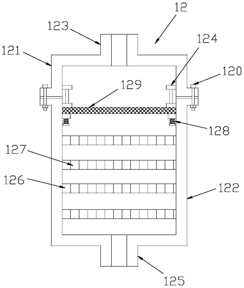
[0030] Example 2: See Figure 3-6The bottom end of the exhaust pipe 17 extends the outer portion of the heater housing 1 and is connected to an exhaust gas muff member 12, and the exhaust gas muff member 12 includes an upper casing 121 and at the bottom of the upper casing 121. The lower housing 122; the top of the upper housing 121 is provided with an intake port 123, and the intake port 123 is in communication with the exhaust pipe 17 for entering the exhaust gas into the exhaust muffle assembly 12; the upper housing 121 Both side inner walls are provided with a positioning member 124, and the positioning member 124 is configured to press the filter plate 129; the bottom portion of the lower case 122 is provided with air outlet 125 for discharge of gas after purification, muffin; The inner spacing of the lower case 122 is provided with a silencer plate 126, and a plurality of muffle holes 127 are provided on the silencer 126; the inner wall of the lower casing 122 is symmetricall...


PUM


Abstract

The invention belongs to the technical field of internal combustion engines, and particularly discloses a coal mine internal combustion engine heater heat recovery system which comprises a heater shell and a cooling liquid storage box located at the top of the heater shell. An air inlet is formed in the left end of the heater body, a steel cylinder is arranged in the heater shell, a combustion chamber is arranged in the steel cylinder, a mixing chamber is arranged at the position, on one side of the steel cylinder, in the heater shell, and a combustible inlet is formed in the top of the heater shell; a cooling liquid containing cavity is formed in the steel cylinder, and the cooling liquid containing cavity communicates with the cooling liquid storage box through a first cooling liquid circulation pipeline and a second cooling liquid circulation pipeline. Exhaust channels which are communicated with each other are formed in the two ends of the steel cylinder, the ends, facing the mixing chamber, of the exhaust channels are communicated with a collecting ring through connecting pipes, an exhaust pipe is arranged at the bottom end of the collecting ring, and the bottom end of the exhaust pipe extends out of the heater shell and is connected with an exhaust silencing assembly; the heat recovery effect is good, and noise and air pollution are not likely to be caused.

Description

Technical field [0001] The present invention relates to the field of internal combustion engines, in particular a heat recovery system of a coal mine internal combustion engine heater. Background technique [0002] In the winter operation, the open-air coal mine is in winter, it is necessary to heat the antifreeze surrounding the heater by the heat generated by the heater, relying on the circulating water pump to send antifreeze to the cab air conditioning system or engine cylinder set, to provide the cab Heating, and can cause the engine heat to reduce the wear of the engine in winter, but the existing coal mine internal combustion engine heater heat recovery system is only one heat exchange, the heat exchange effect is poor, and the gas temperature of its last discharged gas Still higher, causing heat loss; in addition, the heater is discharged to the gas and air pollution when the heater is combusted. Inventive content [0003] It is an object of the present invention to prov...

Claims


Application Information

Patent Timeline
IPC IPC(8): F24H1/12F24H9/1836F24H9/00F23J15/02B01D46/10B01D46/88F02N19/10F16L55/033
CPCY02A50/2351
Inventor 冀宪成杨海军赵晓娟李娟李志芳刘明臣于永利张光阴续航宇黄倩
Owner BEIFANG WEIJIAMAO COAL POWER CO LTD
Why Eureka
Try Eureka