Container energy storage system voltage detection device
An energy storage system and voltage detection technology, applied in measuring devices, measuring device braking, measuring current/voltage, etc., can solve the problems of voltage detection devices without waterproof, easily damaged components, and low service life, and achieve high practical value , prolong service life, low production cost
- Summary
- Abstract
- Description
- Claims
- Application Information
AI Technical Summary
Problems solved by technology
Method used
Image

Examples
Embodiment 1
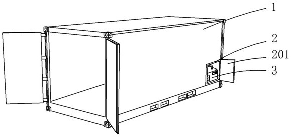
[0030] see Figure 1-3 , the present invention provides a technical solution: a container energy storage system voltage detection device, including a container 1, a storage tank 2 is arranged on the container 1, and a protective cover 201 is movably connected to the outside of the storage tank 2;
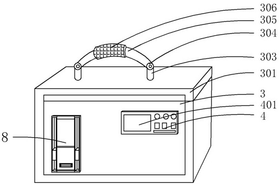
[0031] It should be noted that a pressure measurement box 3 is placed in the placement groove 2, and a box cover 301 is movably connected to the top side of the pressure measurement box 3, and a pair of installation blocks 303 are fixedly connected to the top of the box cover 301, and the top of the installation block 303 is connected by a hinge 304. handle 305;
[0032] It should be noted that the middle part of the handle 305 is connected with a rubber sleeve 306, and the rubber sleeve 306 is provided with anti-skid lines 307;
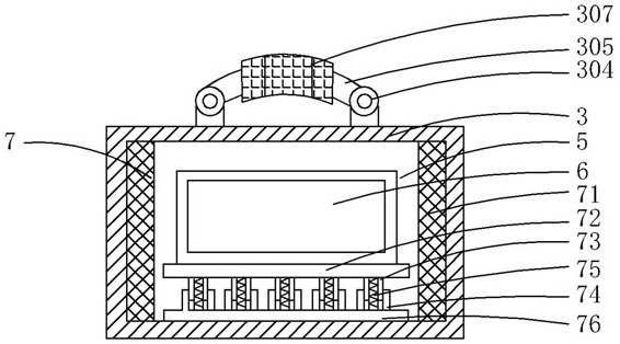
[0033] In addition, an empty slot 5 is arranged inside the pressure measuring box 3 , a pressure measuring device 6 is arranged in the empty slot 5 , and...
Embodiment 2
[0035] see Figure 4 and Figure 6 , is the second embodiment of the present invention, which is based on the previous embodiment;
[0036] Specifically, the buffer assembly 7 contains a sponge pad 71 , a top plate 72 , a limit tube 73 , a limit sleeve 74 , a spring 75 and a bottom plate 76 , and the side of the sponge pad 71 is fixedly connected to the inner wall of the pressure measuring box 3 .
[0037] It should be noted that the bottom of the bottom plate 76 is fixedly connected to the inner bottom surface of the pressure measuring box 3 , and the top of the bottom plate 76 is fixedly connected with a number of limit sleeves 74 .
[0038] It should be noted that the limiting tube 73 is movably connected to the top of the limiting sleeve 74 , the number of the limiting tubes 73 is the same as the number of the limiting sleeve 74 , and the limiting tube 73 is provided with a spring 75 .
[0039] In addition, the top end of the spring 75 is fixedly connected to the inner t...
Embodiment 3
[0046] see Figure 1 to Figure 4 , is the third embodiment of the present invention, which is based on the above two embodiments;
[0047]When the present invention is in use, during the transportation of the container 1, the pressure measuring box 3 is placed in the placement groove 2 in the inner chamber of the container 1, and the pressure measuring device 6 is protected by setting the buffer assembly 7, the spring 75 and the sponge pad 71 can play a buffer role in the transportation process, effectively preventing the pressure gauge 6 and its internal components from being damaged, and the pressure gauge 6 is completely enclosed in the pressure measurement box 3, and the protective component 8 protects the Good interface 86, the slide plate 83 slides onto the interface 86 to play the role of waterproof and anti-collision. During use, slide the slide plate 83 onto the interface 86 to expose the interface 86 and connect the device to be tested with the interface 86 , the vo...
PUM
 Abstract
Description
Claims
Application Information
 - R&D
- Intellectual Property
- Life Sciences
- Materials
- Tech Scout
- Unparalleled Data Quality
- Higher Quality Content
- 60% Fewer Hallucinations
Browse by: Latest US Patents, China's latest patents, Technical Efficacy Thesaurus, Application Domain, Technology Topic, Popular Technical Reports.
© 2025 PatSnap. All rights reserved.Legal|Privacy policy|Modern Slavery Act Transparency Statement|Sitemap|About US| Contact US: help@patsnap.com