Vomitus collecting device for department of hepatobiliary medicine
A technology for collecting device and vomit, which is applied in the field of vomit collecting device for hepatobiliary medicine, can solve the problems of cross infection, vomit odor, trouble, etc., and achieve the effect of preventing secondary discomfort and preventing odor from being emitted.
- Summary
- Abstract
- Description
- Claims
- Application Information
AI Technical Summary
Problems solved by technology
Method used
Image
Examples
Embodiment 1
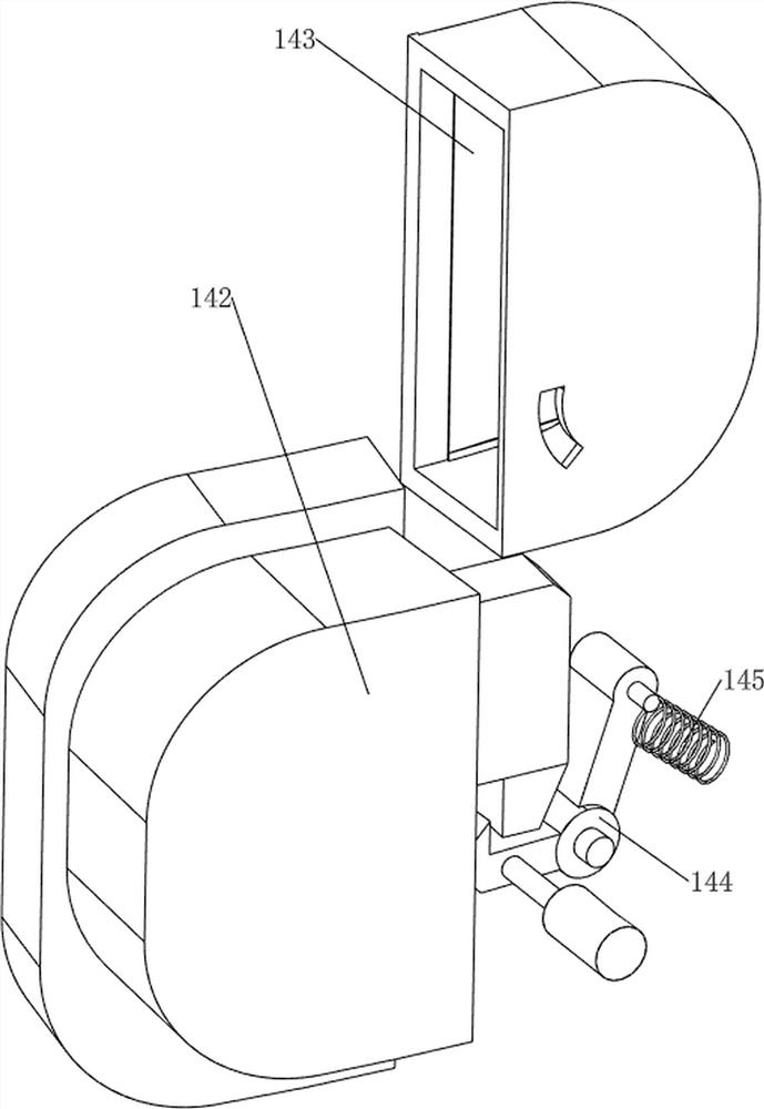
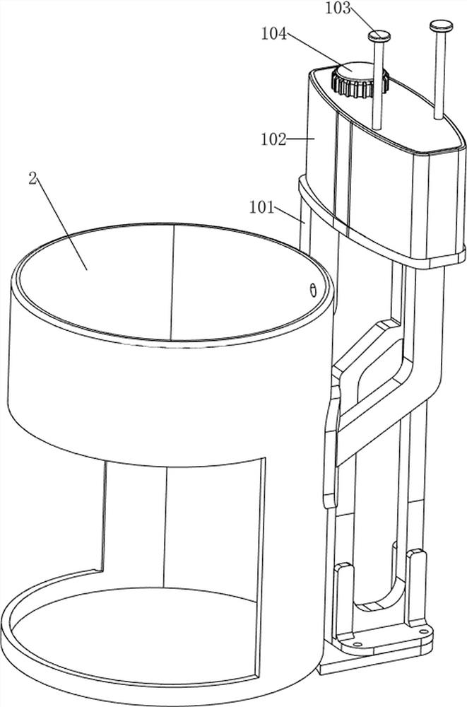
[0034] Such as figure 1 with figure 2 As shown, a vomit collection device for hepatobiliary medicine includes a base 1, a casing 2, a collection bucket 21, a bucket cover 3, a rotating cover 4, a handle 5, a collection plate 6, a sliding cylinder 7, a first telescopic rod 8, The cleaning mechanism 9 and the storage mechanism 10, the base 1 is provided with the casing 2, the collection bucket 21 is placed inside the casing 2, the bucket cover 3 is arranged on the top of the casing 2 in a rotating manner, and the The top of the barrel cover 3 is rotatably provided with the rotatable cover 4, the top of the rotatable cover 4 is provided with the rotatable handle 5, the upper part of the housing 2 is provided with the collecting plate 6, and the bottom end of the collecting plate 6 is sliding. The sliding cylinder 7 is provided, and the sliding cylinder 7 is slidably matched with the top of the collection bucket 21. The first telescopic rod 8 is symmetrically arranged between th...
Embodiment 2
[0037] Such as image 3 , Figure 4 , Figure 5 with Image 6As shown, on the basis of Embodiment 1, the cleaning mechanism 9 includes a water pipe 91, a spray head 92, a first rotating rod 93 and a gasket 94. A rotary valve is provided, the left end of the water pipe 91 is provided with the nozzle 92, the nozzle 92 is located in the collecting plate 6, the valve front side of the water pipe 91 is provided with the first rotating rod 93, the first rotating rod 93 and The barrel cover 3 cooperates, and a cam is arranged on the first rotating rod 93 , and the gasket 94 is rotatably arranged between the first rotating rod 93 and the water pipe 91 .
[0038] The bung 3 rotates upwards and extrudes the first rotating rod 93 to rotate to the left. The first rotating rod 93 rotates to the left to drive the valve to rotate and communicate with the water pipe 91. The water in the storage mechanism 10 then flows into the water pipe 91. It flows out from the nozzle 92 through the wat...
Embodiment 3
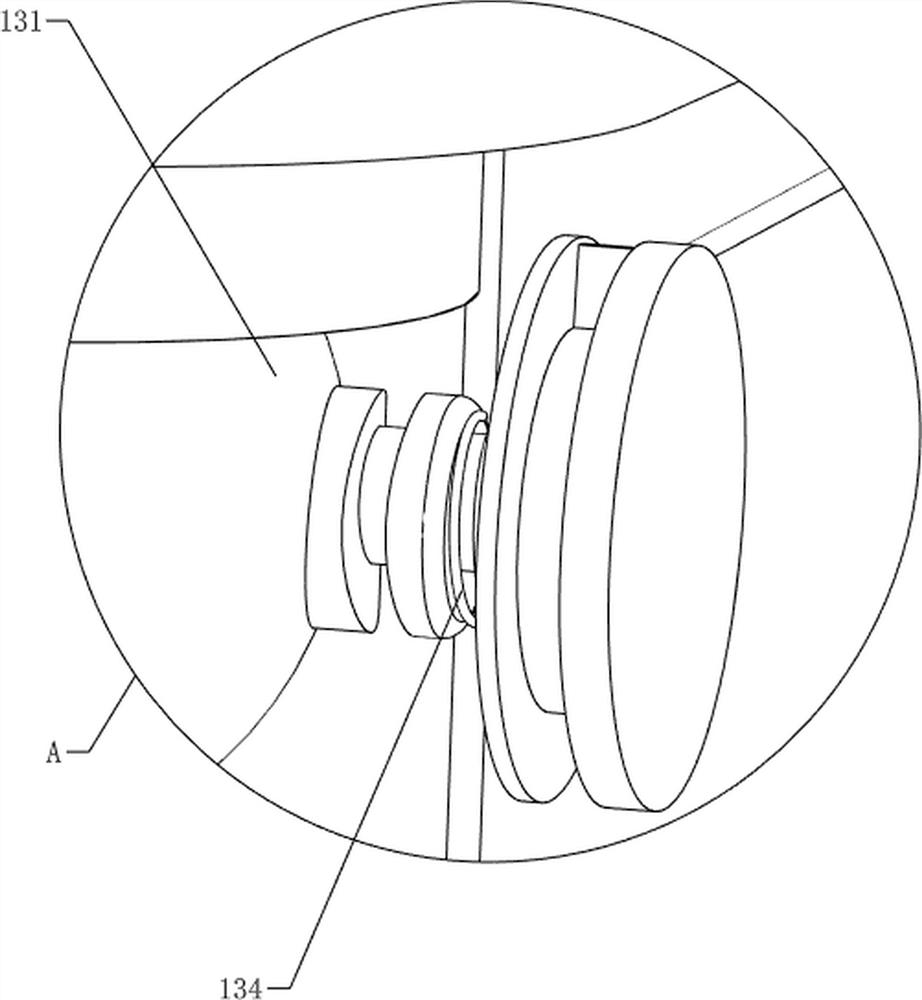
[0042] Such as Figure 7 , Figure 8 , Figure 9 , Figure 10 , Figure 11 , Figure 12 with Figure 13 As shown, on the basis of Embodiment 2, a pressurizing mechanism 11 is also included, and the pressurizing mechanism 11 includes a second rotating rod 111, a first torsion spring 112, a connecting rod 113, a pressurizing valve 114 and a first compression The spring 115, the second rotating rod 111 is arranged in a rotating manner on the upper part of the first bracket 101, the first torsion spring 112 is arranged between the second rotating rod 111 and the first bracket 101, and the second The connecting rod 113 is hinged on the upper part of the rotating rod 111, the pressurizing valve 114 is arranged on the water pipe 91, and a piston rod is slidably arranged in the pressurizing valve 114, and the right end of the piston rod of the pressurizing valve 114 is connected with the connecting rod 113 The first compression spring 115 is arranged between the pressurizing val...
PUM
 Abstract
Description
Claims
Application Information
 - R&D
- Intellectual Property
- Life Sciences
- Materials
- Tech Scout
- Unparalleled Data Quality
- Higher Quality Content
- 60% Fewer Hallucinations
Browse by: Latest US Patents, China's latest patents, Technical Efficacy Thesaurus, Application Domain, Technology Topic, Popular Technical Reports.
© 2025 PatSnap. All rights reserved.Legal|Privacy policy|Modern Slavery Act Transparency Statement|Sitemap|About US| Contact US: help@patsnap.com


