

Power supply circuit with emitter current negative feedback
A technology of power supply circuit and negative feedback, which is applied in the direction of conversion equipment, electrical components, and adjustment of electrical variables without intermediate conversion to AC. It can solve the problems of low operating frequency and slow transmission speed of differential circuits, and achieve speed and frequency improvement. Solve the effect of time delay
Pending Publication Date: 2022-04-19
王仲季
View PDF0 Cites 0 Cited by
- Summary
- Abstract
- Description
- Claims
- Application Information
AI Technical Summary
Problems solved by technology
[0004] In order to overcome the low operating frequency of the differential circuit formed by the common emitter circuit and the slow transmission speed during the negative feedback of the large loop, the present invention designs a current negative feedback circuit composed of the common base circuit, which is used to replace the original common emitter differential voltage negative feedback circuit
Method used
View moreImage
Smart ImageViewing Examples

Examples
Embodiment Construction
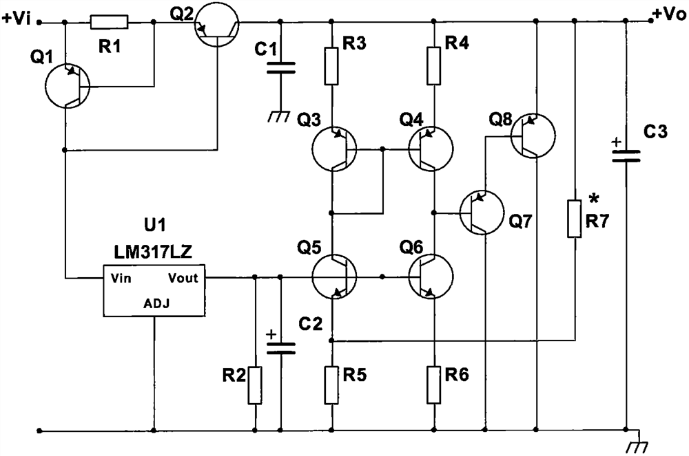
[0010] This circuit takes the Vi of the attached drawing as the input terminal, and its circuit connection method is: Vi→Q1 emitter, collector→U1 Vin terminal (ADJ grounded)→Vout terminal→R2 (the other terminal grounded)→Q5, Q6 base , Vi→R1→Q2 emitter, collector→R3→Q3 emitter, collector (collector→Q3, Q4 base)→Q5 collector, emitter→R5→ground, Q2 collector→R4→Q4 emitter Pole, collector→Q7 base→Q6 collector, emitter→R6→ground, Q2 collector→Q8 emitter, collector→ground, Q8 base→Q7 emitter, collector→ground, Q2 collector→ R7→R5 upper end. Q2 collector → Vo terminal.
Login to View More PUM
 Abstract
The invention designs a power supply circuit with emitter current negative feedback, which is used for solving the problem that the reaction speed of an existing voltage-stabilized power supply following a subordinate load is slow, and the technical scheme for solving the problem is that the voltage of a differential connection large loop in an original power supply circuit is subjected to negative feedback; the large loop current negative feedback formed by common-base connection of the Q5, the Q6, the R5 and the R6 is changed, so that the speed and the frequency of the large loop current negative feedback from the R7 loop connected with the Vo end to the base end of the Q7 are greatly improved, and the problems that time delay is generated in the large loop negative feedback process, the power supply tracking speed is low, and the output frequency is low are solved. And the voltage stabilizing circuit can be integrated in a three-terminal voltage stabilizing block to reduce the volume. The high-speed power supply is mainly used in the field of high-speed power supplies.
Description
technical field [0001] The invention relates to a common-base conversion circuit with emitter negative feedback, which belongs to the analog electronic technology and is mainly used in power circuits requiring high-speed transmission, especially relates to a common-base inverting input stage negative feedback instead of common-emitter differential A circuit with negative feedback on the inverting input stage. [0002] It belongs to analog electronic technology and is mainly used in the field of high-speed power supply. Background technique [0003] A power supply is an essential circuit that provides energy to a circuit. At present, in the digital age, circuits are developing towards high frequency and high speed. The analog power supply circuit connected to the digital circuit power supply in the past, whether it is a three-terminal regulated power supply or a power supply circuit composed of discrete components, can no longer adapt to the development of the current era. ...
Claims
Login to View More Application Information
Patent Timeline
 Patent Type & AuthorityApplications(China)
IPC IPC(8): H02M3/04H02M3/158
CPCH02M3/04H02M3/158
Inventor王仲季
Owner王仲季