Flue gas denitration system and method
A flue gas and denitrification technology, applied in the field of flue gas denitrification system, can solve the problem that nitrogen oxides cannot be fully contacted with ammonia water, etc., and achieve the effect of improving reaction efficiency
- Summary
- Abstract
- Description
- Claims
- Application Information
AI Technical Summary
Problems solved by technology
Method used
Image

Examples
Embodiment 1
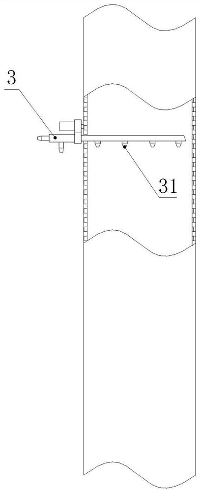
[0035] combine figure 1 , the present embodiment provides a flue gas denitrification system, including a flue gas diversion channel, an ammonia spray gun 3 is inserted in the flue gas diversion channel, and there is a gap between the length direction of the ammonia water spray gun 3 and the drainage direction of the flue gas diversion channel. At a predetermined angle, the ammonia water spray gun 3 is provided with a plurality of spray heads 31 at intervals along the length direction of the ammonia water spray gun 3 , and the spray direction of the spray heads 31 is opposite to the drainage direction of the flue gas drainage channel or the included angle is an obtuse angle.
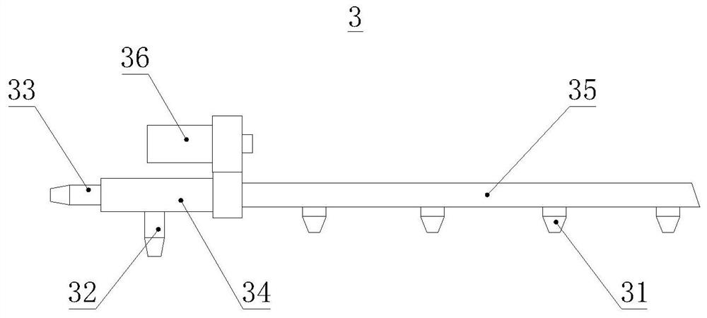
[0036] combine figure 2 Specifically, the ammonia water spray gun 3 is provided with a compressed air interface 32 and an ammonia water interface 33, so that the ammonia water and compressed air are mixed and sent into the spray gun at the same time through the principle of a vacuum generator, so that it...
Embodiment 2
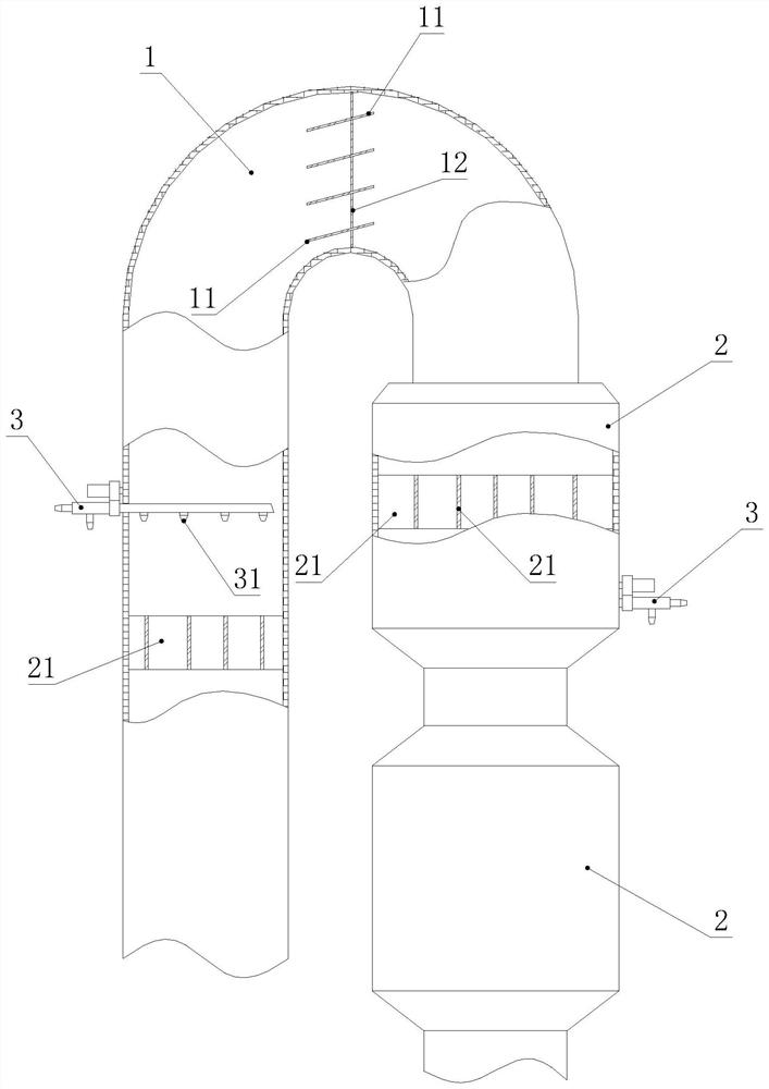
[0044] combine image 3 , this embodiment provides a flue gas denitrification system. Based on the structure and principle of Embodiment 1, the flue gas diversion channel includes a connecting elbow 1, and a plurality of flow guides are arranged inside the turning section of the connecting elbow 1 Blades 11, the two ends of the guide vanes 11 are respectively fixedly connected with the side wall of the connecting elbow 1, and the guide vanes 11 are inclined to the bending direction of the connecting elbow 1, so that the flue gas flows toward the Connect the flow in the bend direction of the elbow.
[0045] It can be understood that the number of guide vanes 11 is set according to the pipe diameter of the connecting elbow 1 , and generally, the number of guide vanes 11 is 3-6 pieces.
[0046] In order to ensure that the guide vane 11 has sufficient strength, it also includes a reinforcing rib beam 12, and the length direction of the reinforcing rib beam 12 is at an angle with ...
Embodiment 3
[0052] This embodiment provides a flue gas out-of-market system. Based on the structure and principle described in Embodiment 2, the inlet end of the connecting elbow 1 is connected with a connecting straight pipe 2, and the connecting straight pipe 2 is provided with a flow equalizer 21 The width direction of the flow equalizers 21 is parallel to the length direction of the connecting straight pipe 2, and the flow equalizers 21 are arranged in a criss-cross pattern in a grid.
[0053] When this embodiment is in use, the flue gas passes through the grid-shaped first flow equalizer 21 in the connecting straight pipe 2 and is preliminarily evenly split and mixed, and then passes through the connecting elbow 1 and then guides the flow guide vanes 11 to overcome the deflection. problem, it can ensure the uniformity of flue gas flow, thereby further improving the uniformity of mixing nitrogen oxides and ammonia water in the flue gas, further improving the reaction efficiency of ammo...
PUM
 Abstract
Description
Claims
Application Information
 - R&D
- Intellectual Property
- Life Sciences
- Materials
- Tech Scout
- Unparalleled Data Quality
- Higher Quality Content
- 60% Fewer Hallucinations
Browse by: Latest US Patents, China's latest patents, Technical Efficacy Thesaurus, Application Domain, Technology Topic, Popular Technical Reports.
© 2025 PatSnap. All rights reserved.Legal|Privacy policy|Modern Slavery Act Transparency Statement|Sitemap|About US| Contact US: help@patsnap.com