Bionic blade for stirring non-Newtonian fluid

A non-Newtonian fluid, stirring blade technology, applied in the field of bionic blades, can solve the problems of reduced operating stability, damage, and blade structure fatigue of the stirring system, and achieves the improvement of blade working efficiency, reduction of turbulent state, and ease of fluid action. Effect

Active Publication Date: 2022-04-22
JIANGSU UNIV ZHENJIANG RES INST OF FLUID ENG EQUIP TECH +1
View PDF5 Cites 1 Cited by
  • Summary
  • Abstract
  • Description
  • Claims
  • Application Information

AI Technical Summary

Problems solved by technology

[0003] Mechanical agitation is used for material blending, mass transfer, mixing, etc. It is often used in food, chemical, construction and other industries. The fluid mixed by agitation is often a non-Newtonian fluid. During the stirring process, due to the special rheological properties of non-Newtonian fluid, and the fluid is generally in a turbulent state, it is very easy to induce the secondary flow in the tank and the large-scale vortex around the impeller, resulting in stable operation of the stirring system The stability is greatly reduced, and the agitator will cause fatigue and damage to the blade structure under the condition of long-term use
[0004] With the development of bionic technology and the mixing industry, more and more attention has been paid to the cross-discipline in various fields. Previously, bionic technology was mostly used in the fan and pump industries, but it was not fully developed and applied in the mixing industry. Therefore, a non-Newtonian mixer for mixing is designed Fluid bionic blades are necessary to solve the above problems

Method used


Image

  • Bionic blade for stirring non-Newtonian fluid
  • Bionic blade for stirring non-Newtonian fluid
  • Bionic blade for stirring non-Newtonian fluid

Examples


Embodiment Construction

[0028] In order to make the object, technical solution and advantages of the present invention clearer, the present invention will be further described in detail below in conjunction with the accompanying drawings and embodiments. It should be understood that the specific embodiments described here are only used to explain the present invention, not to limit the present invention.

[0029] The present invention will be further elaborated below in conjunction with accompanying drawing:

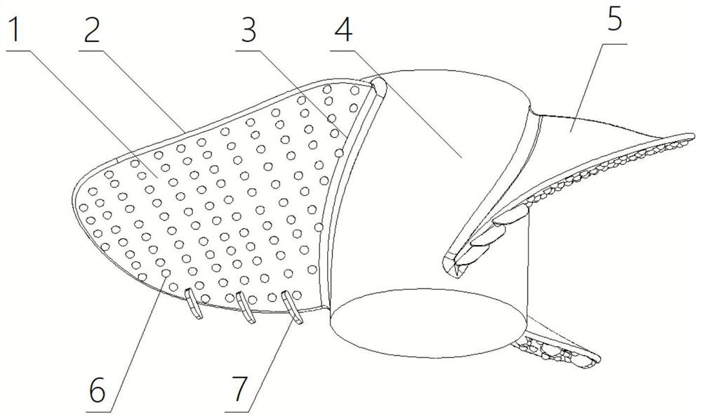
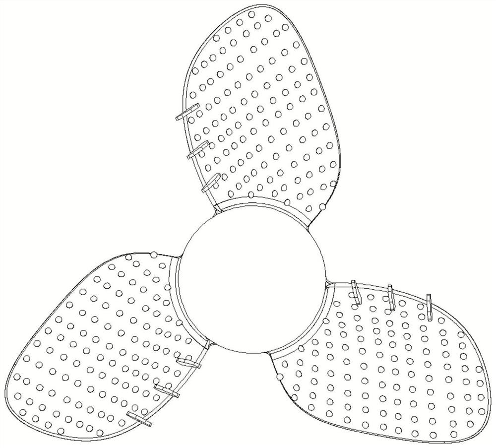
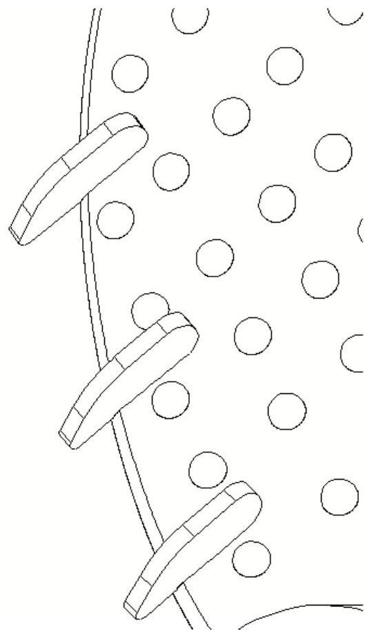
[0030] As shown in the figure, a bionic stirring paddle includes a blade body, the blade body includes a working surface 1, an outer edge 2, a smooth joint at the tail of the blade 3, a paddle shaft 4 attached to the blade, a back pressure surface 5, and a working surface of the blade Raised hemispherical structure 6, wing structure 7 at the tail end of the blade. The blade number Z=3 of the blade is distributed along the axis. The diameter of the bionic blade is d, the overall diameter of the...


PUM


Abstract

The invention discloses a bionic blade structure for stirring non-Newtonian fluid, which comprises a working surface of a blade body, a back pressure surface, an outer edge, a smooth joint of a blade tail part, a paddle shaft attached to the blade, a blade working surface raised hemisphere structure and a blade tail end wing structure. The non-smooth hemispherical structure of the working face of the blade can effectively reduce the impact resistance of high-viscosity fluid to the surface of the blade, meanwhile, large vortexes generated by incoming flow are cut and guided into countless small vortexes, liquid is fully stirred and separated, the wing structure at the tail end of the blade can reduce the incoming flow resistance, and the blade is more stable. And the wake flow flowing state is effectively improved and guided. After the bionic stirring blade is repeatedly tested and demonstrated through Fluent software, for example, the stirring liquid is a CMC solution with the concentration of 0.85%, the rotating speed of the stirring paddle is 150 rpm, compared with a smooth blade profile without a bionic structure, the average speed of the stirring fluid is increased by 0.005 m / s, the torque is reduced by 0.02 N.m, the stirring effect is improved, and the novel concept of developing the green and environment-friendly industry is met.

Description

[0001] Technical field [0002] The invention relates to the stirring field, in particular to a bionic blade for stirring non-Newtonian fluids. Background technique [0003] Mechanical agitation is used for material blending, mass transfer, mixing, etc. It is often used in food, chemical, construction and other industries. The fluid mixed by agitation is often a non-Newtonian fluid. During the stirring process, due to the special rheological properties of non-Newtonian fluid, and the fluid is generally in a turbulent state, it is very easy to induce the secondary flow in the tank and the large-scale vortex around the impeller, resulting in stable operation of the stirring system The performance is greatly reduced, and the stirring blade will cause fatigue and damage to the blade structure under the condition of long-term use. [0004] With the development of bionic technology and the mixing industry, more and more attention has been paid to the cross-discipline in various fie...

Claims


Application Information

Patent Timeline
Patent Type & Authority Applications(China)
IPC IPC(8): B01F27/112B01F27/053
Inventor 王鹏王世基司乔瑞李盾
Owner JIANGSU UNIV ZHENJIANG RES INST OF FLUID ENG EQUIP TECH
Why Eureka
Try Eureka