Steel belt bearing vertical roll turning device
A bearing and vertical roller technology, which is used in turning equipment, positioning devices, auxiliary devices, etc., can solve the problems of poor braking transmission effect, debris collection, and difficulty in fixing, so as to improve machining accuracy, improve turning accuracy, and improve product quality. quality effect
- Summary
- Abstract
- Description
- Claims
- Application Information
AI Technical Summary
Problems solved by technology
Method used
Image

Examples
Embodiment 1
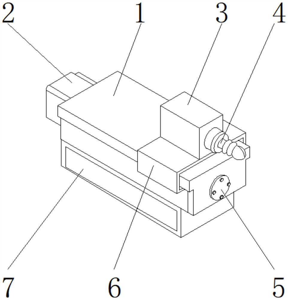
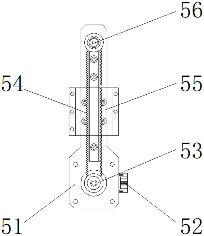
[0029] Such as Figure 1-5 As shown, the present invention provides a vertical roller turning device for steel belt bearings, which includes a main body 1, an internal bearing 6 is arranged on the upper end of the main body 1, and a vertical roller shaft 3 is arranged on the upper end of the internal bearing 6, and one side of the vertical roller shaft 3 A clamping device 4 is provided, a debris collection device 7 is provided at the lower end of the main body 1, a transmission device 5 is provided on one side of the main body 1, and a positioning device 2 is provided on the other side of the main body 1; the transmission device 5 includes a brake pedal 51 , motor 52, driving wheel 53, synchronous toothed belt 54, ball screw 55, driven wheel 56, driving wheel 53 is positioned at the front end of brake pedal 51, and motor 52 is positioned at the side of brake pedal 51; Brake pedal 51 and Bolts are arranged between the motors 52, one side of the brake pedal 51 is fixedly connect...
Embodiment 2
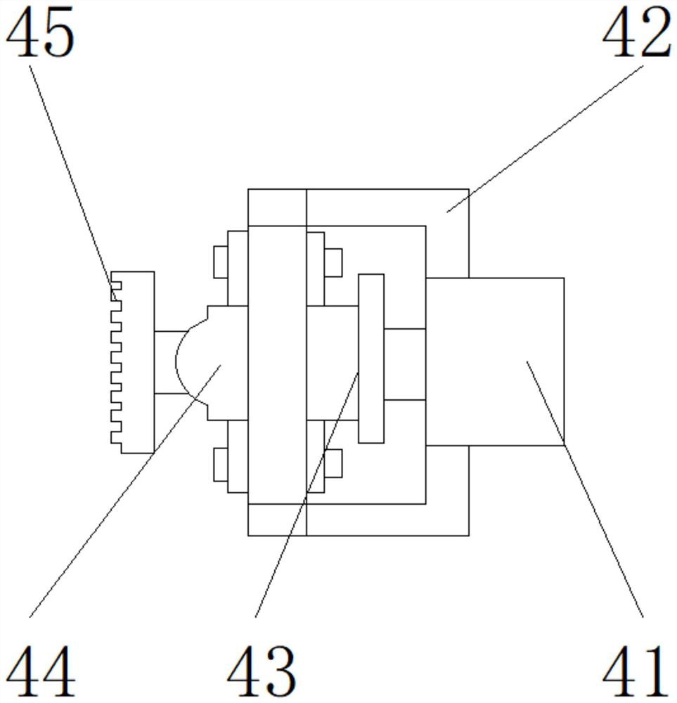
[0032] Such as Figure 1-5 As shown, on the basis of Embodiment 1, the present invention provides a technical solution: preferably, the clamping device 4 includes a rotary oil cylinder 41, a fixed frame 42, a power shaft 43, a rotary joint 44, and a locking toothed disc 45. The oil cylinder 41 is located on one side of the fixed frame 42, the power shaft 43 is located on the inner side of the fixed frame 42, the rotary joint 44 is located on one side of the power shaft 43, and the locking tooth plate 45 is located on one side of the rotary joint 44, and the fixed frame 42 and the rotary oil cylinder Bolts are arranged between 41, one side of the fixed frame 42 is fixedly connected with one side of the rotary cylinder 41 by bolts, a thread groove is arranged between the rotary cylinder 41 and the power shaft 43, and one side of the rotary cylinder 41 is connected with the power through the thread groove. One side of the shaft 43 is detachably connected, and a notch is arranged be...
Embodiment 3
[0035] Such as Figure 1-5 As shown, on the basis of Embodiment 1, the present invention provides a technical solution: preferably, the debris collection device 7 includes a suction cylinder 71, a delivery pipe 72, a pin shaft 73, a feed hole 74, a collection box 75, Magnet 76, conveying pipeline 72 is positioned at the lower end of suction tube 71, and bearing pin 73 is positioned at the side of conveying pipeline 72, and collecting box 75 is positioned at the lower end of conveying pipeline 72, and feeding hole 74 is positioned at the upper end outer surface of collecting box 75, and magnet 76 Located on one side of the collection box 75, a welding block is arranged between the delivery pipe 72 and the suction barrel 71, the upper end of the delivery pipe 72 is fixedly connected to the lower end of the suction barrel 71 through the welding block, and between the delivery pipe 72 and the pin shaft 73 A notch is provided, and one side of the delivery pipe 72 is detachably conn...
PUM
 Abstract
Description
Claims
Application Information
 - R&D
- Intellectual Property
- Life Sciences
- Materials
- Tech Scout
- Unparalleled Data Quality
- Higher Quality Content
- 60% Fewer Hallucinations
Browse by: Latest US Patents, China's latest patents, Technical Efficacy Thesaurus, Application Domain, Technology Topic, Popular Technical Reports.
© 2025 PatSnap. All rights reserved.Legal|Privacy policy|Modern Slavery Act Transparency Statement|Sitemap|About US| Contact US: help@patsnap.com