Hydraulic station with cooling system

A technology of hydraulic station and hydraulic oil tank, applied in the field of hydraulic system, can solve the problems of low efficiency, poor cooling effect of oil temperature, unfavorable cooling of hydraulic oil, etc., so as to increase cooling efficiency, improve heat exchange efficiency, and increase heat The effect of swapping areas

Active Publication Date: 2022-04-22
南通油顺液压机械有限公司
View PDF9 Cites 0 Cited by
  • Summary
  • Abstract
  • Description
  • Claims
  • Application Information

AI Technical Summary

Problems solved by technology

[0008] The invention provides a hydraulic station with a cooling system, one of which is to provide a cooling chamber, an auxiliary cooling pipe, a refrigerant inlet pipe, a heat exchange assembly, a refrigerant outlet pipe, and an auxiliary refrigerant passage pipe, so as to solve the problem of the existing hydraulic station. When in use, most of the air-cooled coolers used for cooling work have a poor cooling effect on the oil temperature, and the efficiency is not high, which is not conducive to the rapid cooling of the hydraulic oil.

Method used


Image

  • Hydraulic station with cooling system
  • Hydraulic station with cooling system
  • Hydraulic station with cooling system

Examples


Embodiment 1

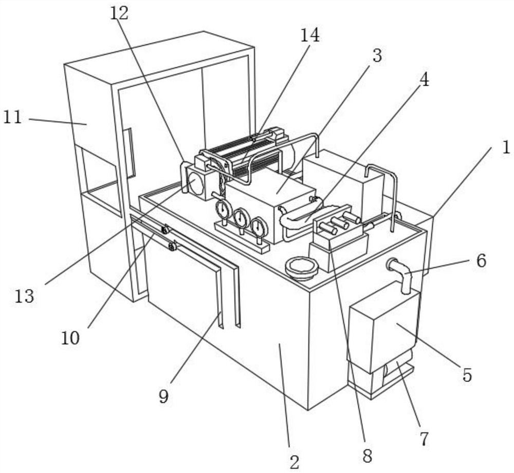
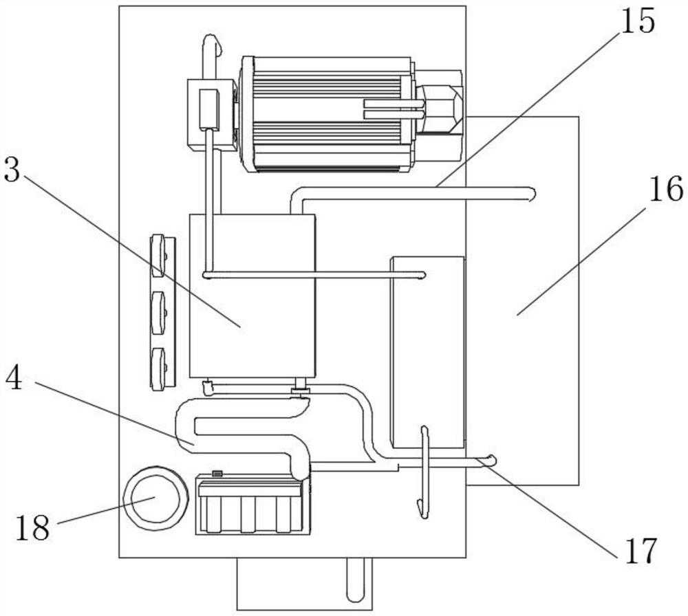
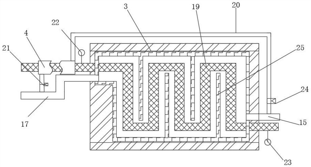
[0038] Such as Figure 1-7 As shown, the present invention provides a hydraulic station with a cooling system, including a main body device 1, a hydraulic oil tank 2 is arranged inside the main body device 1, a cooling chamber 3 is fixedly connected to the upper surface of the hydraulic oil tank 2, and the right side of the hydraulic oil tank 2 The side is provided with an external circulating filter assembly 5, the left side of the hydraulic oil tank 2 is provided with a noise reduction protective cover 11, the inner wall of the cooling chamber 3 is movably connected with an oil delivery pipe 19, and the outer wall of the left end of the oil delivery pipe 19 is provided with an auxiliary cooling pipe 4, the cooling chamber 3 The inner wall of the cooling chamber 3 is fixedly connected with a built-in partition 25, the right side of the cooling chamber 3 is fixedly connected with a refrigerant inlet pipe 15, the left side of the cooling chamber 3 is fixedly connected with a ref...

Embodiment 2

[0045] Such as Figure 1-7 As shown, on the basis of Embodiment 1, the present invention provides a technical solution: preferably, the outer wall of the filter extraction pipe 29 is fixedly connected with an auxiliary filter inlet pipe 32, and the auxiliary filter inlet pipe 32 is movable away from one end of the filter extraction pipe 29 Connected with a first filter core 36, the top of the first filter core 36 is movably connected with an auxiliary filter delivery pipe 33, the outer wall of the auxiliary filter delivery pipe 33 is fixedly connected with a second electromagnetic control valve 35, and the outer wall of the auxiliary filter inlet pipe 32 A first electromagnetic control valve 34 is fixedly connected, a filter pump 7 is fixedly connected to the tail end of the filter extraction pipe 29 , and a first pressure detector 30 is fixedly connected to the outer wall of one end of the filter extraction pipe 29 .

[0046] The inner wall of the noise-reducing protective co...


PUM


Abstract

The invention discloses a hydraulic station with a cooling system, and relates to the technical field of hydraulic systems, the hydraulic station comprises a main body device, a hydraulic oil tank is arranged in the main body device, the upper surface of the hydraulic oil tank is fixedly connected with a cooling chamber, and the right side of the hydraulic oil tank is provided with an external circulating filtering assembly; a noise reduction protective cover is arranged on the left side of the hydraulic oil tank, and an oil conveying pipe is movably connected to the inner wall of the cooling chamber. Through the cooling chamber, the auxiliary cooling pipe, the heat exchange assembly, the refrigerant outlet pipe and the auxiliary refrigerant through pipe, the problems that when an existing hydraulic station is used, most air-cooled coolers are adopted for cooling work, the oil temperature cooling effect is poor, efficiency is not high, and rapid cooling of hydraulic oil is not facilitated are solved; refrigerant is shunted and conveyed into the auxiliary cooling pipe and is matched with the arc-shaped heat dissipation fins for secondary cooling treatment of hydraulic oil, and then the arc-shaped heat dissipation fins and the heat dissipation through holes are used for improving the heat exchange efficiency.

Description

technical field [0001] The invention relates to the technical field of hydraulic systems, in particular to a hydraulic station with a cooling system. Background technique [0002] The hydraulic station is also called the hydraulic pump station. The motor drives the oil pump to rotate. The pump pumps oil after absorbing oil from the oil tank, and converts the mechanical energy into the pressure energy of the hydraulic oil. After the flow is adjusted, it is transmitted to the oil cylinder or oil motor of the hydraulic machine through the external pipeline, thereby controlling the change of the direction of the hydraulic machine, the magnitude of the force and the speed of the speed, and pushing various hydraulic machines to do work. The hydraulic station is an independent hydraulic device. It supplies oil according to the requirements of the driving device (main engine), and controls the direction, pressure and flow of oil flow. It is suitable for various hydraulic machines wh...

Claims


Application Information

Patent Timeline
Patent Type & Authority Applications(China)
IPC IPC(8): F15B21/00F15B21/041F15B21/0423F15B19/00G10K11/162
CPCF15B21/00F15B21/0423F15B21/041F15B19/00G10K11/162
Inventor 汪勇
Owner 南通油顺液压机械有限公司
Why Eureka
Try Eureka