
Two-cavity type heat conduction switch for extremely low temperature equipment and extremely low temperature equipment

An ultra-low temperature, cavity-type technology, applied in the field of two-cavity thermal conduction switches and ultra-low temperature equipment, can solve problems such as unknown reliability and achieve the effect of high thermal conduction efficiency

Pending Publication Date: 2022-04-26
格物致寒(苏州)科学仪器有限公司
View PDF0 Cites 3 Cited by
  • Summary
  • Abstract
  • Description
  • Claims
  • Application Information

AI Technical Summary

Problems solved by technology

However, the mechanical thermal switch will add moving parts to the refrigerator environment, considering the influence of deformation caused by temperature changes, the reliability in long-term use is unknown

Method used


Image

  • Two-cavity type heat conduction switch for extremely low temperature equipment and extremely low temperature equipment
  • Two-cavity type heat conduction switch for extremely low temperature equipment and extremely low temperature equipment

Examples


Embodiment 1

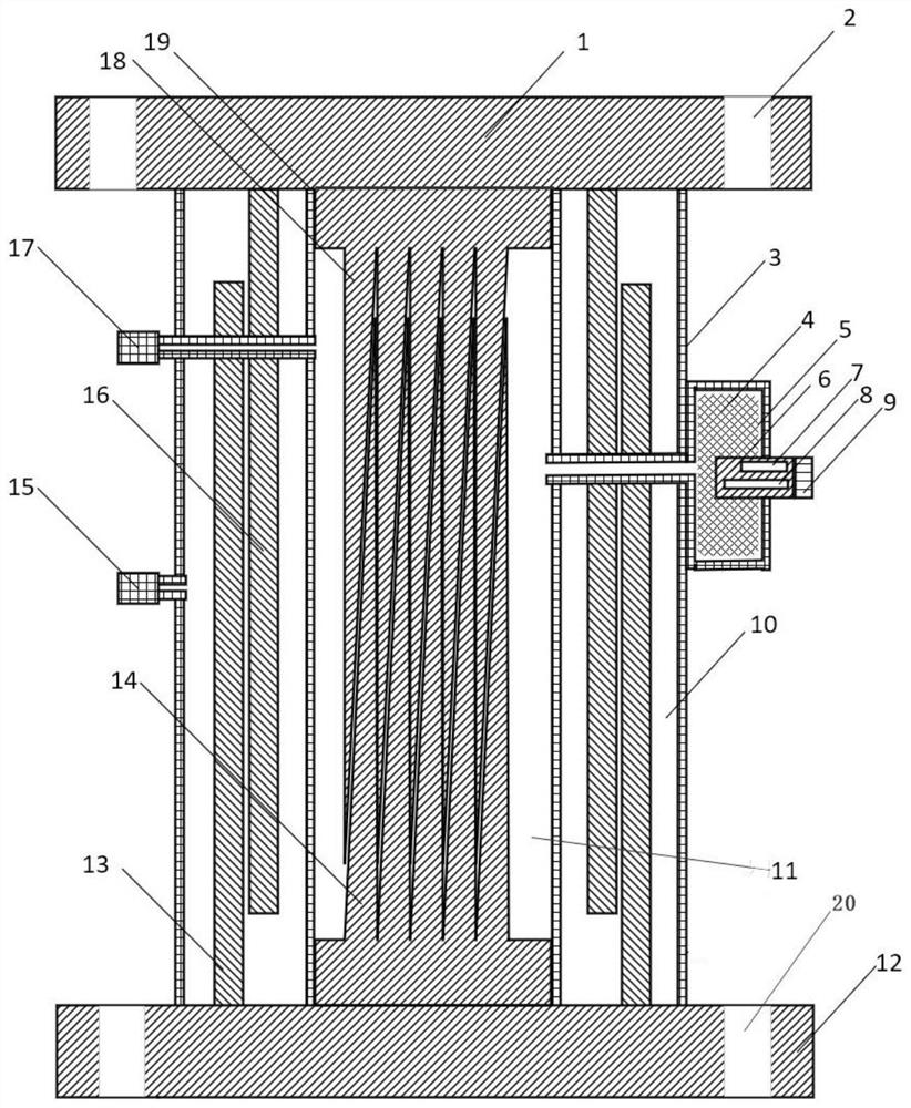
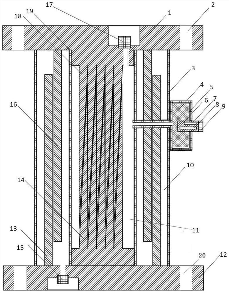
[0046] This embodiment provides a two-cavity heat conduction switch (hereinafter referred to as a thermal switch) for extremely low temperature equipment, wherein, in the field of low temperature equipment, extremely low temperature refers to equipment that can provide a temperature range below 1K, such as figure 1 As shown, it includes: an upper fixing plate 1, a lower fixing plate 12, an outer cavity wall 3 and an inner cavity wall 19;

[0047] The outer cavity wall 3 is arranged between the upper fixed plate 1 and the lower fixed plate 12, and the three form a closed cavity, that is, an external cavity 10; the external cavity 10 is provided with an external cavity heat conduction device And the two constitute an external switch;

[0048] The inner cavity wall 19 is arranged between the upper fixing plate 1 and the lower fixing plate 12, and the three form a closed cavity, that is, the inner cavity 11, and the inner cavity wall 19 is arranged on the outer cavity wall. 3. In...

Embodiment 2

[0076] This embodiment provides an extremely low temperature device, in which the two-cavity heat conduction switch for the extremely low temperature device described in any one of Embodiment 1 is set.

[0077] In summary, the present invention provides a two-cavity heat conduction switch for extremely low temperature equipment. The heat switch combines an active heat switch and a passive heat switch to achieve a two-stage cooling effect. The main feature of the thermal switch is that the thermal switch mainly has a double-layer chamber structure, and two different working media are used in the two chambers: such as helium and nitrogen, so that the thermal switch can have two switching points. In the cooling process of extremely low temperature equipment, in order to have a higher thermal conductivity in the high temperature area, the nitrogen in the outer cavity is in a gaseous state, and the thermal switch is turned on. After reaching the nitrogen liquefaction temperature, th...


PUM

PropertyMeasurementUnit
Gapaaaaaaaaaa

Abstract

The invention discloses a two-cavity heat conduction switch for extremely low temperature equipment and the extremely low temperature equipment wherein the two-cavity heat conduction switch for the extremely low temperature equipment comprises an upper fixing plate, a lower fixing plate, an outer cavity wall and an inner cavity wall; the outer cavity wall is arranged between the upper fixing plate and the lower fixing plate, and the outer cavity wall, the upper fixing plate and the lower fixing plate form a closed cavity, namely an outer cavity; an external chamber heat conduction device is arranged in the external chamber; the inner cavity wall is arranged between the upper fixing plate and the lower fixing plate, the inner cavity wall, the upper fixing plate and the lower fixing plate form a closed cavity, namely an inner cavity, and the inner cavity wall is arranged in the outer cavity wall; and an internal chamber heat conduction device is arranged in the internal chamber. According to the invention, the active thermal switch and the passive thermal switch are combined, and two thermal switches with different temperature intervals are combined, so that different thermal conduction effects in a high-temperature area and a low-temperature area can be achieved, higher thermal conduction efficiency can be obtained in the high-temperature area, and a low-temperature system can be cooled more quickly in the high-temperature area.

Description

technical field [0001] The invention relates to the field of low-temperature switches, and more specifically, relates to a two-cavity heat conduction switch for extremely low-temperature equipment and the extremely low-temperature equipment. Background technique [0002] With the rise of quantum computing, countries around the world have a lot of research and development in quantum computing; in material science, the quantum behavior of new materials at extremely low temperatures has been extensively studied by condensed matter physicists around the world; in the field of detectors, Countries are developing new forms of high-resolution photon and radiation detectors. Whether it's quantum computers, condensed-matter physics research, or new detectors, the research being done requires the extremely low temperatures provided by dilution refrigerators. [0003] However, the current problems faced by the dilution refrigerator are that the equipment is large, the heating and cool...

Claims


Application Information

Patent Timeline
IPC IPC(8): F28F13/00
CPCF28F13/00F28F2013/008Y02B30/00
Inventor 王永超郝镇齐张磊
Owner 格物致寒(苏州)科学仪器有限公司
Learn More