
Adjustable spectrum correction system and method

A spectrum and bias adjustment technology, applied in the field of interferometer systems, which can solve problems such as inability to swing arm correction

Active Publication Date: 2022-04-26
HANGZHOU CHUNLAI TECH
View PDF5 Cites 0 Cited by
  • Summary
  • Abstract
  • Description
  • Claims
  • Application Information

AI Technical Summary

Problems solved by technology

[0005] The purpose of the present invention is to overcome the problem in the prior art that the existing interferometer system cannot correct the abnormalities generated during the swinging process of the swing arm in time when the external vibration or the ground is tilted, and provides an interferometer system that can offset the environmental vibration , and the adjustable spectrum correction system and method that can adjust the magnitude of the current and center the swing arm for the inclined ground

Method used


Image

  • Adjustable spectrum correction system and method
  • Adjustable spectrum correction system and method
  • Adjustable spectrum correction system and method

Examples


Embodiment 1

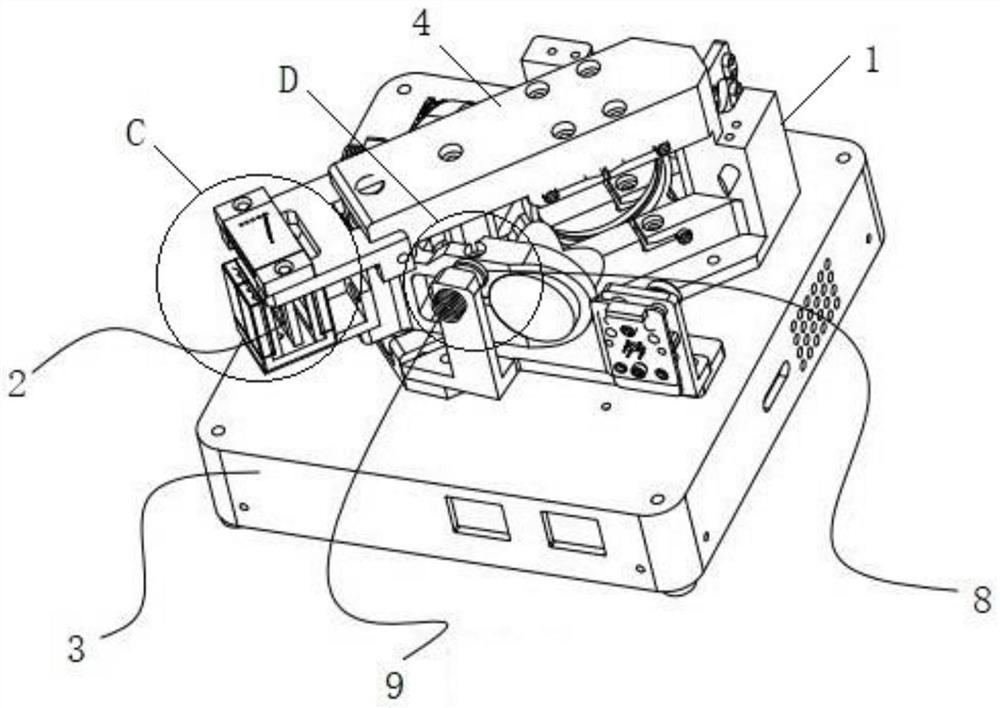
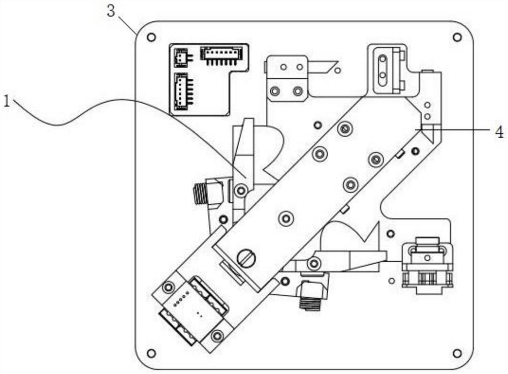
[0037] Such as figure 1 with figure 2 The tunable spectral correction system shown consists of:

[0038] Swing device 1, including swing arm 4;

[0039] The swing driving device 2 is used for correcting the swing arm through voltage regulation;

[0040] The control circuit device 3 contains a control circuit for controlling the operation of the swing device;

[0041] High-frequency working device, used to continuously generate vibration after electrification.

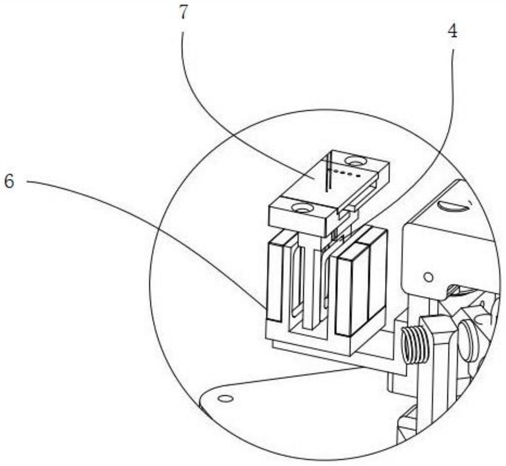
[0042] Further, such as image 3 As shown, the swing drive device is located on the swing arm; the swing drive device includes a energized coil 5, a permanent magnet 6 arranged on both sides of the energized coil and a drive circuit 7 arranged above the energized coil; the drive circuit and the energized coil electrical connection. The current direction is continuously switched through the energized coil to generate a magnetic field to offset the abnormal swing, and because the permanent magnet is installed on th...


PUM


Abstract

The invention belongs to the technical field of interferometer systems, and particularly relates to an adjustable spectrum correction system and method. The system comprises a swing device, a swing driving device, a control circuit device and a high-frequency working device. The method comprises the following steps: S1, inputting triangular wave current, and judging whether an interference peak is centered or not; if not, turning to the step S2; s2, starting bias adjustment, and judging whether the first data separator is A or B; s3, if the data separator is A, determining the data separator as a rising edge, and if the swing arm deviates leftwards, increasing a bias parameter; if the swing arm deviates rightwards, the bias voltage parameter is reduced; s4, if the data separator is B, determining the data separator as a falling edge; if the swing arm deviates leftwards, the bias voltage parameter is reduced; if the swing arm deviates rightwards, the bias voltage parameter is increased; and S5, when the position of the swing arm after deviation rectification is in the middle, the deviation rectification process is completed. The device has the advantages that environment vibration can be counteracted, and the magnitude of current can be adjusted according to the inclined ground, so that the swing arm is centered.

Description

technical field [0001] The invention belongs to the technical field of interferometer systems, and in particular relates to an adjustable spectrum correction system and method. Background technique [0002] At present, in the interferometer system, external vibration or ground tilt will cause abnormalities in the swinging process of the swing arm, which will lead to spectral anomalies and seriously affect the spectral performance. [0003] Therefore, it is very necessary to design an adjustable spectrum correction system and method that can not only offset the environmental vibration, but also adjust the magnitude of the current to make the swing arm centered. [0004] For example, the application number is CN201320374721.X, a kind of miniature Fourier transform spectrometer described in the Chinese patent literature, including a light source, an interference system, the interference system includes a first beam splitter, a moving mirror, a fixed mirror, the light emitted by...

Claims


Application Information

Patent Timeline
Patent Type & Authority Applications(China)
IPC IPC(8): G01J3/45G01J3/02
CPCG01J3/45G01J3/0289G01J3/0297G01J2003/2866
Inventor 于志伟张建清邱梦春张涵汪鲁见
Owner HANGZHOU CHUNLAI TECH
Learn More