Low-temperature bending detection equipment and method for metal material
A technology of low-temperature bending and metal materials, which is applied in the direction of analyzing materials, preparing samples for testing, and testing the strength of materials by applying stable bending force. It can solve problems such as uneven temperature distribution, low temperature, and measurement temperature deviation, and achieve Avoid cooling dead angle, the effect of uniform temperature distribution
- Summary
- Abstract
- Description
- Claims
- Application Information
AI Technical Summary
Problems solved by technology
Method used
Image

Examples
Embodiment 1
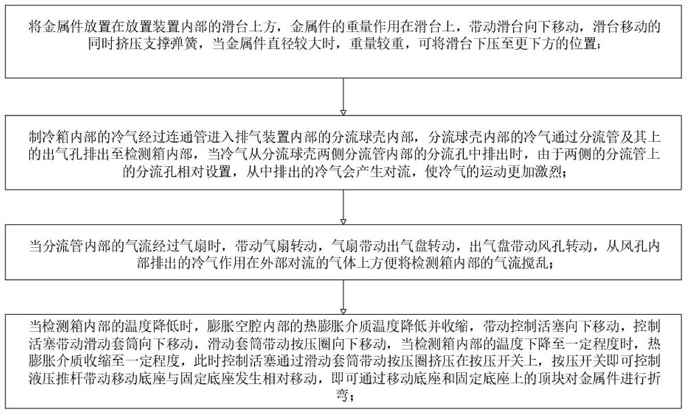
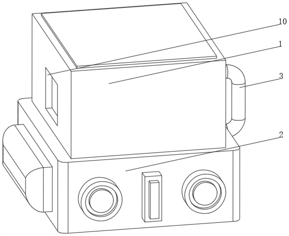
[0045] see Figure 2-4 , the present invention provides a technical solution: a low-temperature bending detection device for metal materials, specifically comprising:
[0046] A detection box 1, the bottom of the detection box 1 is provided with a refrigeration box 2, the refrigeration box 2, and the top communicates with the inside of the detection box 1 through a connecting pipe 3;
[0047] Exhaust device 4, the exhaust device 4 is arranged inside the detection box 1, the bottom of the exhaust device 4 communicates with the top of the connecting pipe 3;
[0048] The mobile base 5 is provided with a fixed base 6 on both sides of the mobile base 5, a hydraulic push rod 7 is fixedly connected to one side of the mobile base 5, and a top block 8 is fixedly connected to the top of the mobile base 5 and the fixed base 6. The side is fixedly connected with a supporting device 9;
[0049] Observation port 10, the observation port 10 is arranged at the position facing the support de...
Embodiment 2
[0058] see Figure 2-5 On the basis of the first embodiment, the present invention provides a technical solution: the support device 9 includes a support seat 91, an expansion cavity 92 is opened inside the support seat 91, and a control sleeve 93 is communicated with the top of the expansion cavity 92, and the control sleeve The inner wall of 93 is slidably connected with a control piston 94, the top of the control sleeve 93 is fixedly connected with a fixed seat 95, the top of the fixed seat 95 is threaded and connected with a control rod 96, and the control rod 96 is provided with a sliding sleeve 97 on the outside. The top of 97 is fixedly connected with a pressing ring 98, one end of the control rod 96 located inside the sliding sleeve 97 is fixedly connected with a pressing switch 99, one side of the support seat 91 is fixedly connected with the top block 8, and the inside of the expansion cavity 92 is filled with thermal expansion medium. The bottom of the sleeve 97 is ...
Embodiment 3
[0061] see Figure 2-6 , on the basis of Embodiment 1 and Embodiment 2, the present invention provides a technical solution: the placement device 90 includes a connection base 901, the bottom of the connection base 901 is fixedly connected with a heat conduction sheet 902, and the end of the heat conduction sheet 902 away from the connection base 901 penetrates and expands The cavity 92 extends to the inside of the expansion cavity 92. A chute 903 is provided on one side of the connecting seat 901. The inner wall of the chute 903 is slidably connected to a slide table 904. A support spring 905 is arranged between the bottom of the slide table 904 and the chute 903. One side of the connection seat 901 is fixedly connected with the side of the control sleeve 93, the top of the slide table 904 is arranged in an arc shape, the connection seat 901 and the slide table 904 are made of heat-conducting materials, the bottom of the support spring 905 is fixedly connected with the bottom ...
PUM
 Abstract
Description
Claims
Application Information
 - R&D
- Intellectual Property
- Life Sciences
- Materials
- Tech Scout
- Unparalleled Data Quality
- Higher Quality Content
- 60% Fewer Hallucinations
Browse by: Latest US Patents, China's latest patents, Technical Efficacy Thesaurus, Application Domain, Technology Topic, Popular Technical Reports.
© 2025 PatSnap. All rights reserved.Legal|Privacy policy|Modern Slavery Act Transparency Statement|Sitemap|About US| Contact US: help@patsnap.com