LED packaging substrate and LED packaging equipment using same

A technology of LED packaging and packaging substrates, which is applied in the direction of semiconductor devices, electrical components, circuits, etc., can solve the problems of affecting light transmission efficiency, reducing the service life of LEDs, and aging of packaging glue, so as to enhance the heat dissipation effect and alleviate equipment damage. The effect of enhancing the connection strength

Pending Publication Date: 2022-04-26
江苏国中芯半导体科技有限公司
View PDF16 Cites 1 Cited by
  • Summary
  • Abstract
  • Description
  • Claims
  • Application Information

AI Technical Summary

Problems solved by technology

[0002] LED packaging technology is mostly developed and evolved on the basis of discrete device packaging technology, but it has great particularity. Under normal circumstances, the die of discrete devices is sealed in the package body, and the function of the package is mainly to protect the tube. Core and complete the electrical interconnection, while LED packaging is to complete the output electrical signal and protect the normal operation of the die. Generally speaking, the function of the package is to provide sufficient protection for the chip to prevent the chip from failing due to long-term exposure in the air or mechanical damage. In order to improve the stability of the chip, for the LED package, it also needs to have good light extraction efficiency and good heat dissipation. A good package can make the LED have better luminous efficiency and heat dissipation environment, thereby improving the life of the LED. High-power LED packaging Due to the complex structure and process, which directly affect the performance and life of the LED, especially the packaging of high-power white LEDs is a hot spot among research hotspots. If the internal input cannot be quickly dissipated, the junction temperature will be too high, which will lead to A series of problems such as reduced light intensity, spectral shift, increased color temperature, increased thermal stress, and accelerated aging of the chip will greatly reduce the service life of the LED, and will also cause accelerated aging of the packaging gel filled on the chip, affecting its transparency. At the same time, the bottom plate and metal heat sink of the existing LED package are all planar structures. This structure not only leads to a small contact area, but also cannot fully contact with the heat dissipation silicone grease, resulting in poor heat dissipation effect and Phenomena of poor stability

Method used


Image

  • LED packaging substrate and LED packaging equipment using same
  • LED packaging substrate and LED packaging equipment using same

Examples


Embodiment 1

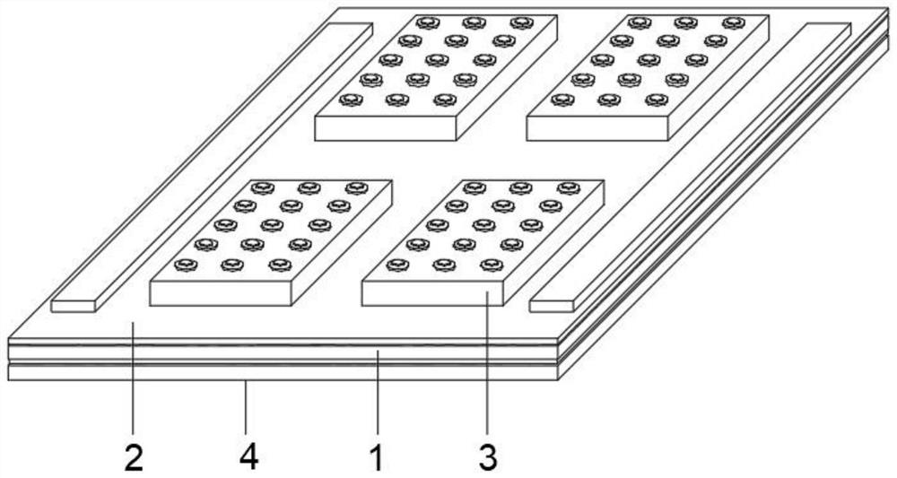
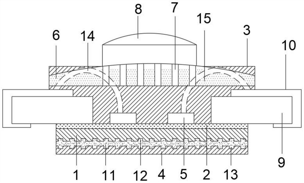
[0021] like figure 1 and figure 2 As shown, the present invention provides a technical solution: LED packaging substrate and LED packaging equipment using the LED packaging substrate, including LED base plate 1, packaging frame 3, metal heat sink 4, LED chip 5 and phosphor powder 15, LED base plate 1 Metal heat sink 4 is provided at the bottom, first grooves 12 are equally spaced inside the LED base plate 1, and second grooves 13 are equally spaced inside the metal heat sink 4, which can improve the filling effect of heat dissipation silicone grease, thereby enhancing the LED base plate 1 the connection strength and heat dissipation effect with the metal heat sink 4, the top of the LED base plate 1 is equipped with a packaging frame 3, the inside of the packaging frame 3 is symmetrically and fixedly connected with a packaging substrate 9, and the tops of the two packaging substrates 9 are equipped with a printed circuit board 10, The LED chip 5 is mounted on the top of the L...

Embodiment 2

[0028] like figure 1 and figure 2 As shown, the present invention provides a technical solution: including LED base plate 1, package frame 3, metal heat sink 4, LED chip 5 and phosphor powder 15, metal heat sink 4 is provided at the bottom of LED base plate 1, and the interior of LED base plate 1 is equidistant A first groove 12 is opened, and a second groove 13 is equidistantly opened inside the metal heat sink 4. A packaging frame 3 is mounted on the top of the LED base plate 1, and a packaging substrate 9 is fixedly connected to the inside of the packaging frame 3 symmetrically. Two packaging substrates 9 The top is equipped with a printed circuit board 10, the LED chip 5 is installed on the top of the LED bottom plate 1 and between the two packaging substrates 9, and the inside of the packaging frame 3 is provided with a silicone layer 6 directly above the printed circuit board 10. The silicone layer Light-transmitting holes 7 are equidistantly opened inside 6 , and fluo...

Embodiment 3

[0031] like figure 1 and figure 2 As shown, a metal reflector 2 is provided between the top of the LED base plate 1 and the packaging frame 3; the top of the packaging frame 3 is fixedly connected with a resin lens 8 directly above the light transmission hole 7; the tops of the two printed circuit boards 10 are fixed A wire 14 is connected, and the end of the wire 14 away from the printed circuit board 10 is fixedly connected to the LED chip 5 ; a heat dissipation silicone grease layer 11 is provided between the LED base plate 1 and the metal heat sink 4 .

[0032] In this embodiment, the scattered light source can be reflected by the metal reflector 2, thereby improving the illumination lumen of the LED assembly; the LED chip 5 can be protected by the resin lens 8, thereby reducing its loss, which is beneficial to improving the use of the equipment lifespan; the electric current can be transmitted through the wire 14, so that the LED chip 5 can emit light, which can ensure ...


PUM


Abstract

The LED packaging substrate comprises an LED bottom plate, a packaging frame, a metal cooling fin, an LED wafer and fluorescent powder, the metal cooling fin is arranged at the bottom of the LED bottom plate, first grooves are formed in the LED bottom plate at equal intervals, second grooves are formed in the metal cooling fin at equal intervals, the packaging frame is assembled at the top of the LED bottom plate, and the LED wafer is arranged in the packaging frame. According to the LED packaging structure, the second groove and the first groove which are formed in the LED bottom plate and the metal radiator are used in cooperation, the filling effect of heat dissipation silicone grease can be improved, the heat dissipation effect of the LED packaging structure is improved, the heat dissipation efficiency is improved, and the service life of the LED packaging structure is prolonged. And the fluorescent powder arranged in the silica gel layer is matched with the light holes for use, so that the influence of silica gel aging on the light emitting rate can be reduced, and the light transmittance of equipment can be kept.

Description

technical field [0001] The invention relates to LED packaging, in particular to an LED packaging substrate and LED packaging equipment using the LED packaging substrate, and belongs to the technical field of LED packaging. Background technique [0002] LED packaging technology is mostly developed and evolved on the basis of discrete device packaging technology, but it has great particularity. Under normal circumstances, the die of discrete devices is sealed in the package body, and the function of the package is mainly to protect the tube. Core and complete the electrical interconnection, while LED packaging is to complete the output electrical signal and protect the normal operation of the die. Generally speaking, the function of the package is to provide sufficient protection for the chip to prevent the chip from failing due to long-term exposure in the air or mechanical damage. In order to improve the stability of the chip, for the LED package, it also needs to have good ...

Claims


Application Information

Patent Timeline
Patent Type & Authority Applications(China)
IPC IPC(8): H01L33/48H01L33/64H01L33/54H01L33/50H01L33/60
CPCH01L33/486H01L33/642H01L33/505H01L33/54H01L33/60
Inventor 徐代成
Owner 江苏国中芯半导体科技有限公司
Why Eureka
Try Eureka