Three-dimensional planting device

A technology of three-dimensional planting and planting, applied in the fields of agricultural gas emission reduction, botany equipment and methods, agriculture, etc., to achieve the effects of saving water, good growth, and reducing product weight

Pending Publication Date: 2022-04-29
浙江贸美农业科技有限公司
View PDF10 Cites 0 Cited by
  • Summary
  • Abstract
  • Description
  • Claims
  • Application Information

AI Technical Summary

Problems solved by technology

Furthermore, the user can watch or take it at any position, it is very easy and convenient to use and solves the problem of water consumption for planting plants, and adopts a closed circulating waterway to save water resources

Method used


Image

  • Three-dimensional planting device
  • Three-dimensional planting device
  • Three-dimensional planting device

Examples


Embodiment 1

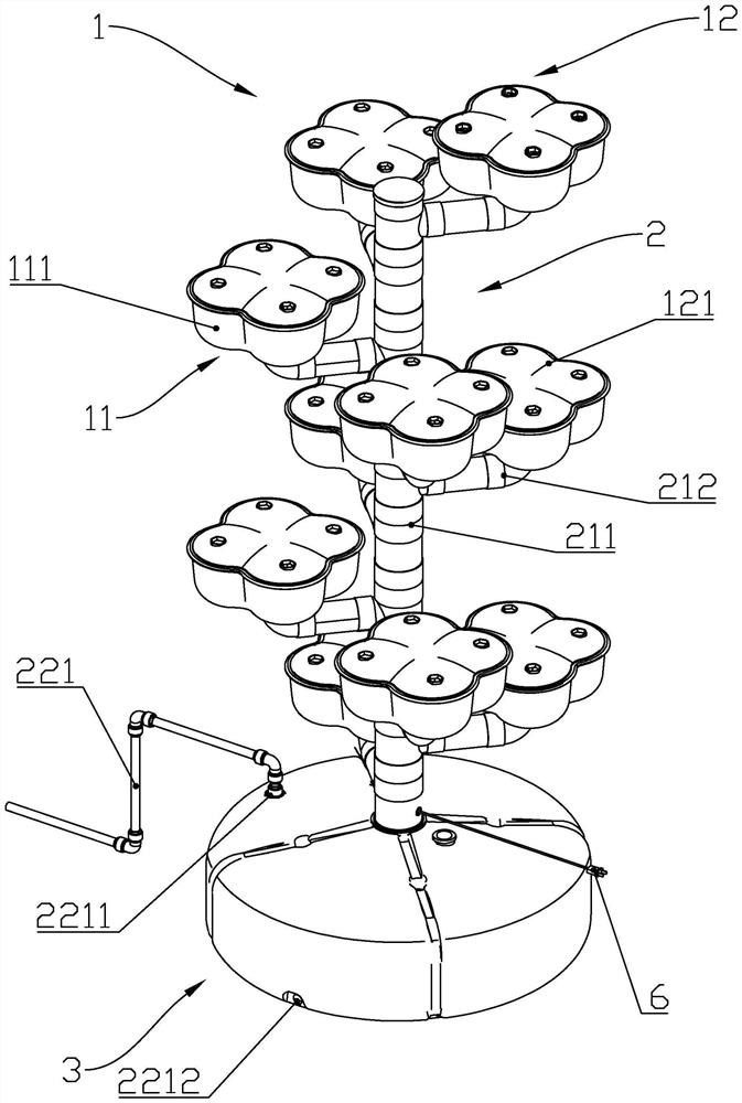
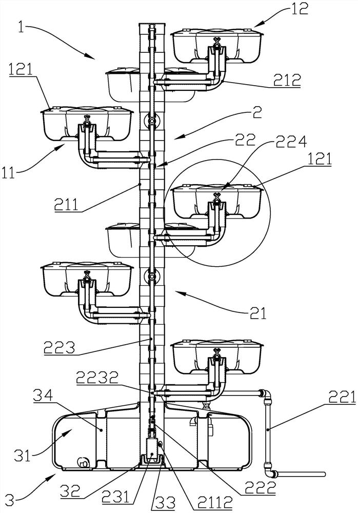
[0086] like Figure 1-Figure 3 As shown, a three-dimensional planting device includes a planting mechanism 1, a pipeline mechanism 2 and a mounting seat 3, and the planting mechanism 1, the pipeline mechanism 2 and the mounting seat 3 are engaged with each other. Thereby in actual use, planting mechanism 1, pipeline mechanism 2 and mounting base 3 are detachably connected.

[0087] from figure 1 It can be seen from the figure that the pipe mechanism 2 has a support member 21 on the outside, which can be divided into a main pipe 211 and a secondary pipe 212 .

[0088] The bottom of the main pipe 211 is connected with the mounting base 3, and the other end is vertically upward; wherein on the outer wall of the main pipe 211, several secondary pipes 212 are installed, which can extend outwards to form a tree shape, increasing the aesthetic feeling of the overall design.

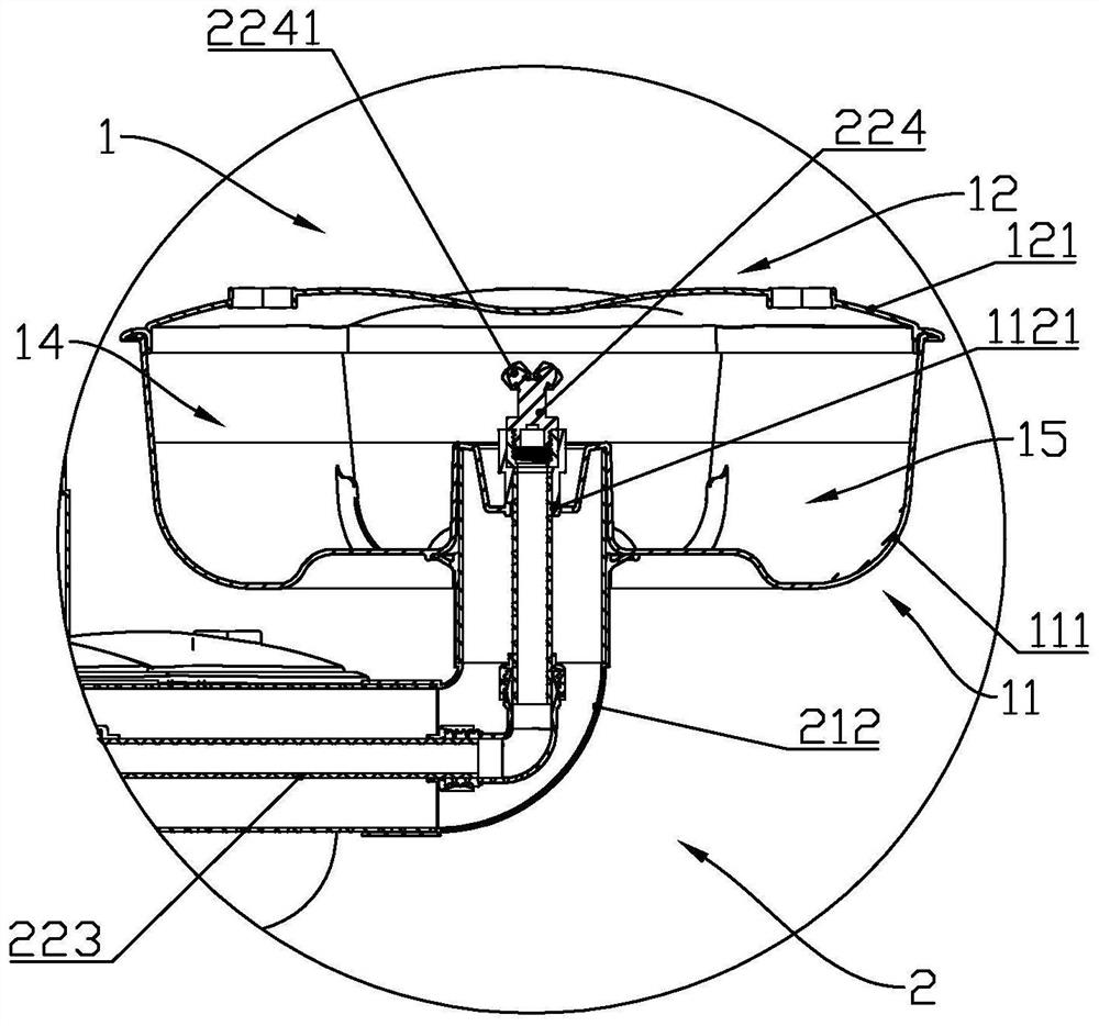
[0089] The pipeline mechanism 2 has a supporting member 21 and a sprinkling member 22, wherein the sprinkli...

Embodiment 1

[0109] [Embodiment 1 Variation 1]

[0110] This modified example is basically consistent with Embodiment 1, the difference lies in:

[0111] Figure 11 is a schematic structural diagram of Modification 1; Figure 12 It is the bottom schematic diagram of Modification 1.

[0112] like Figure 11-12 As shown, in this modified example, the secondary pipeline 212 is canceled, and the planting mechanism 1 is formed around the main pipeline 211 to form a circular planting mechanism 1, and the conveying section 223 directly extends into the planting mechanism 1 for spraying; and under the planting mechanism 1 A secondary pipeline 212 is provided, and the secondary pipeline 212 extends outward around the main pipeline 211, and the secondary pipeline 212 and the main pipeline 211 are rotated and clamped to form a chuck seat 1111, and the upper end of the chuck seat 1111 is connected with the planting mechanism 1, and the chuck seat 1111 drives Planting mechanism 1 rotates.

[0113]...

Embodiment 1

[0114] [Modification Example 2 of Embodiment 1]

[0115] This modified example is basically consistent with Embodiment 1, the difference lies in:

[0116] Figure 13 It is a schematic diagram of the structure of the second modification.

[0117] like Figure 13As shown, in this modified example, the planting device is canceled, the secondary pipeline 212 is extended, and a through hole is provided on the secondary pipeline 212, and the second accommodating chamber 14 is installed.

[0118] Figure 14 It is a schematic structural diagram of the pipeline mechanism 2 of the second modification.

[0119] Such as Figure 14 As shown, the sprinkler 224 is directly installed in the secondary pipeline 212, which can make the moisture in the pipeline flow out directly along the secondary pipeline 212, preventing the water flow from accumulating to block the passage.

[0120] Such a design can reduce costs and reduce the need for installation.


PUM


Abstract

The invention discloses a three-dimensional planting device, and relates to the technical field of planting devices. Comprising a mounting seat used for supporting a planting device; the inner side of the mounting seat is at least provided with a water storage chamber for storing water; the planting mechanisms are used for planting plants; the base is at least provided with a first planting component for placing plants; the pipeline mechanism is used for supporting the planting mechanism and realizing a circulating water path; wherein the pipeline mechanism is at least provided with a supporting component, the supporting component is at least provided with a vertically-arranged main pipeline, one end of the supporting component is connected with the mounting base, the other end of the main pipeline vertically extends upwards, and the two sides of the main pipeline are connected with the multiple planting mechanisms respectively; the sprinkling irrigation component is located in the water storage chamber, the main pipeline and the planting mechanism and used for driving water flow to enter the planting mechanism through the water storage chamber and the main pipeline in sequence; the spray irrigation component and the main pipeline are further provided with a backflow channel which is used for guiding water flow to flow back to the water storage cavity from the planting mechanism.

Description

technical field [0001] The invention belongs to the technical field of planting devices, in particular to a three-dimensional planting device. Background technique [0002] At present, existing plant planting devices have the problems of taking up a large space and being inconvenient to take care of. [0003] For example, there is a Chinese utility model patent, the patent number is 201510511707.3, which discloses an intelligent hydroponic vegetable planting cabinet. [0004] The intelligent hydroponic vegetable planting cabinet includes multiple planting layers, a water circulation system, an air circulation system and a control system. The control system is respectively connected with the water circulation system and the air circulation system to realize automatic water circulation and automatic air circulation. Each planting layer includes a planting box and a planting space. Lighting tubes are installed on the top of the planting space, and adjacent upper layer planting...

Claims


Application Information

Patent Timeline
Patent Type & Authority Applications(China)
IPC IPC(8): A01G31/06
CPCA01G31/06Y02P60/21
Inventor 王四平
Owner 浙江贸美农业科技有限公司
Why Eureka
Try Eureka