
Method of operating a cooling fluid system

a technology of cooling fluid and cooling tower, which is applied in the direction of combustible gas purification/modification, lighting and heating apparatus, and separation processes, etc., can solve the problems of difficult distribution of returned cooling water to all the cells in the cooling tower complex, limiting the production rate of the polymer producing reactor in the plant, and achieving the goal of impossible to achieve. , to achieve the effect of more accurate return water control

Inactive Publication Date: 2008-11-06
EQUSR CHEM LP
View PDF23 Cites 0 Cited by
  • Summary
  • Abstract
  • Description
  • Claims
  • Application Information

AI Technical Summary

Benefits of technology

[0015]This invention provides a simpler, more cost effective, and more reliable method for achieving uniform return water flow across multiple, individual sub-headers by relying on the measurement of water levels in the sub-headers, and not actual water flow volume measurements.
[0017]This invention also provides significantly more accurate return water control through multiple sub-headers in a time period more acceptable in a commercial production plant than that achievable by way of the prior art practice of manually operating individual sub-header control valves using visually observed relative amounts of return water actually flowing through individual cooling cells.

Problems solved by technology

Cooling of the polymer producing reactors in the plant can be a limiting factor for the production rate of those reactors, particularly in the warmer months of the year.
This even distribution of returned cooling water to all the cells in the cooling tower complex is particularly challenging in a gravity-fed return system when the take-off points for the sub-headers from the common header are at different locations along the vertical height of that header.
In reality, this prior art process, because of the hysteresis effect of flowing water as described in greater detail hereinafter, this goal was impossible to achieve in a reasonable period of time, and extremely difficult to achieve even if time was of no consequence, which is never the case in a commercial production plant.
When the return water was taken off from different locations across the height of the common header, the problem of obtaining even flow of return water to all sub-headers was made immeasurably more difficult because it was possible, even probable, that all or a major portion of the return water (see FIG. 4 hereinafter) would be removed from the header by way of less than all of the sub-headers, thereby starving at least one sub-header and its associated cooling cell of return water flow altogether.
This situation puts more return water to be cooled through less than all the cooling cells available in the complex, and prevents the cooling tower complex from achieving its goal of cooling the return water to as close as possible to the ambient temperature surrounding that complex.
One method for solving the even distribution of return water through the sub-headers could arguably be measuring the actual volume of water flowing in each sub-header, but this would entail the use of a complicated system of fluid flow measuring equipment that would be expensive to install and maintain.

Method used


Image

  • Method of operating a cooling fluid system
  • Method of operating a cooling fluid system
  • Method of operating a cooling fluid system

Examples


Embodiment Construction

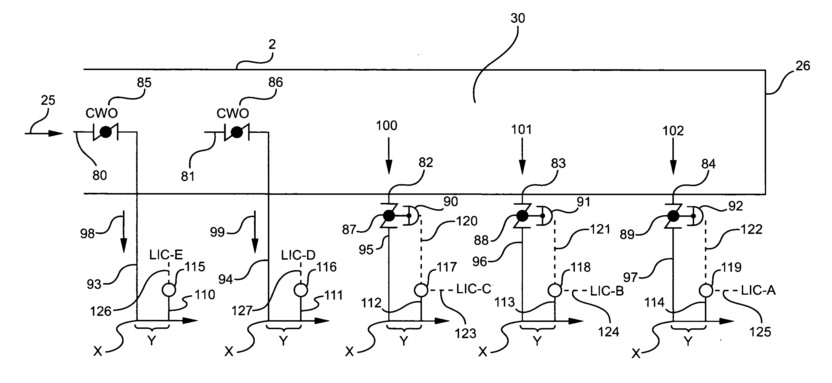
[0024]This invention is based, in part, on the inventive concept that cooling water return flows to a cooling tower complex are essentially balanced when the sub-headers are each partially liquid full, thereby leaving a vapor phase above the liquid surface in each sub-header.

[0025]Further to the inventive concepts of this invention, since the sub-header piping and cooling tower cell construction are similar, the liquid levels in the sub-headers are approximately the same when the return water flows to the cells are balanced. That is to say the flooded (liquid water carrying) cross-sectional area in all the sub-headers is approximately the same, i.e., balanced, as a measure of water flow in the sub-headers without measuring the amount (volume) of water actually flowing in any of the sub-headers.

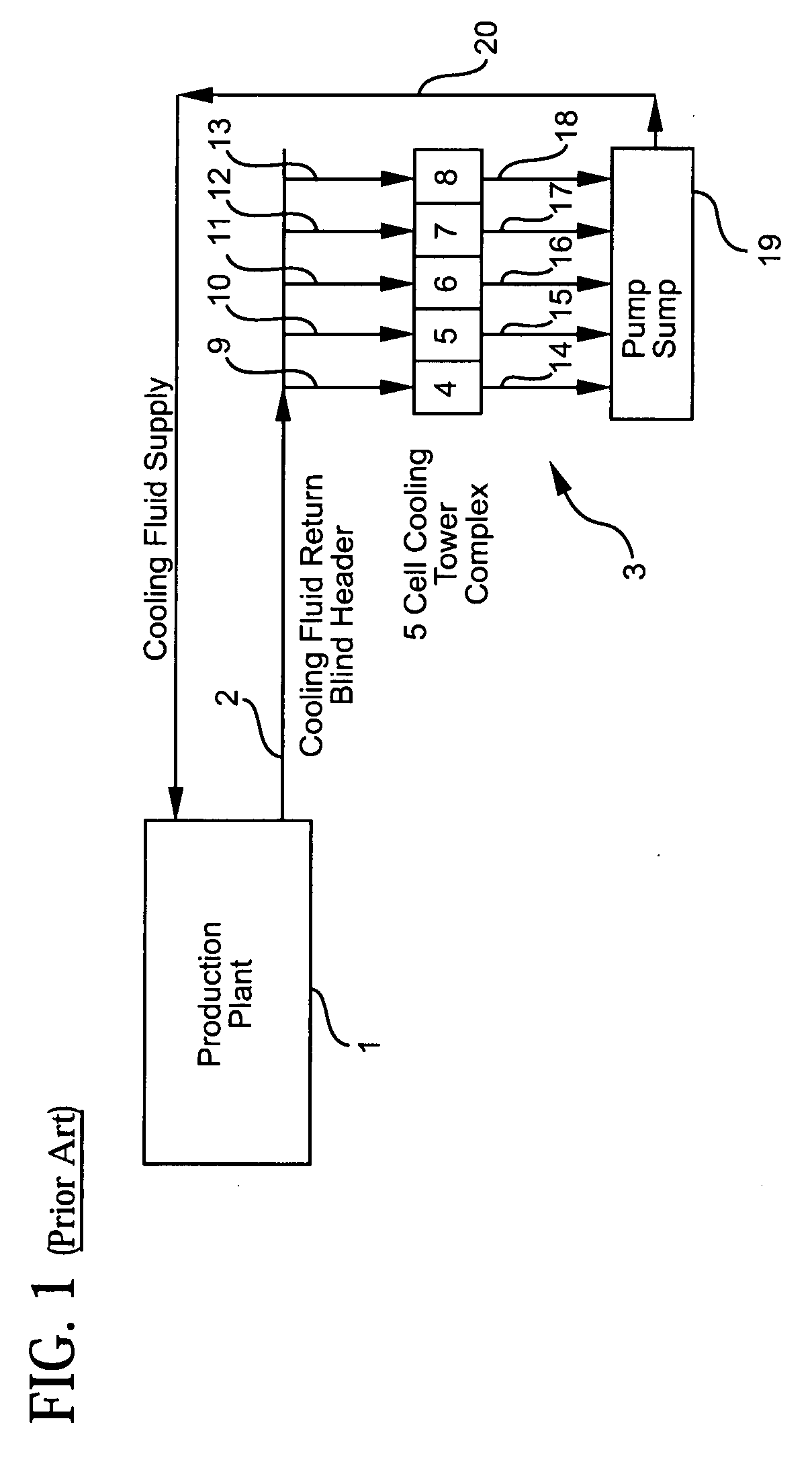
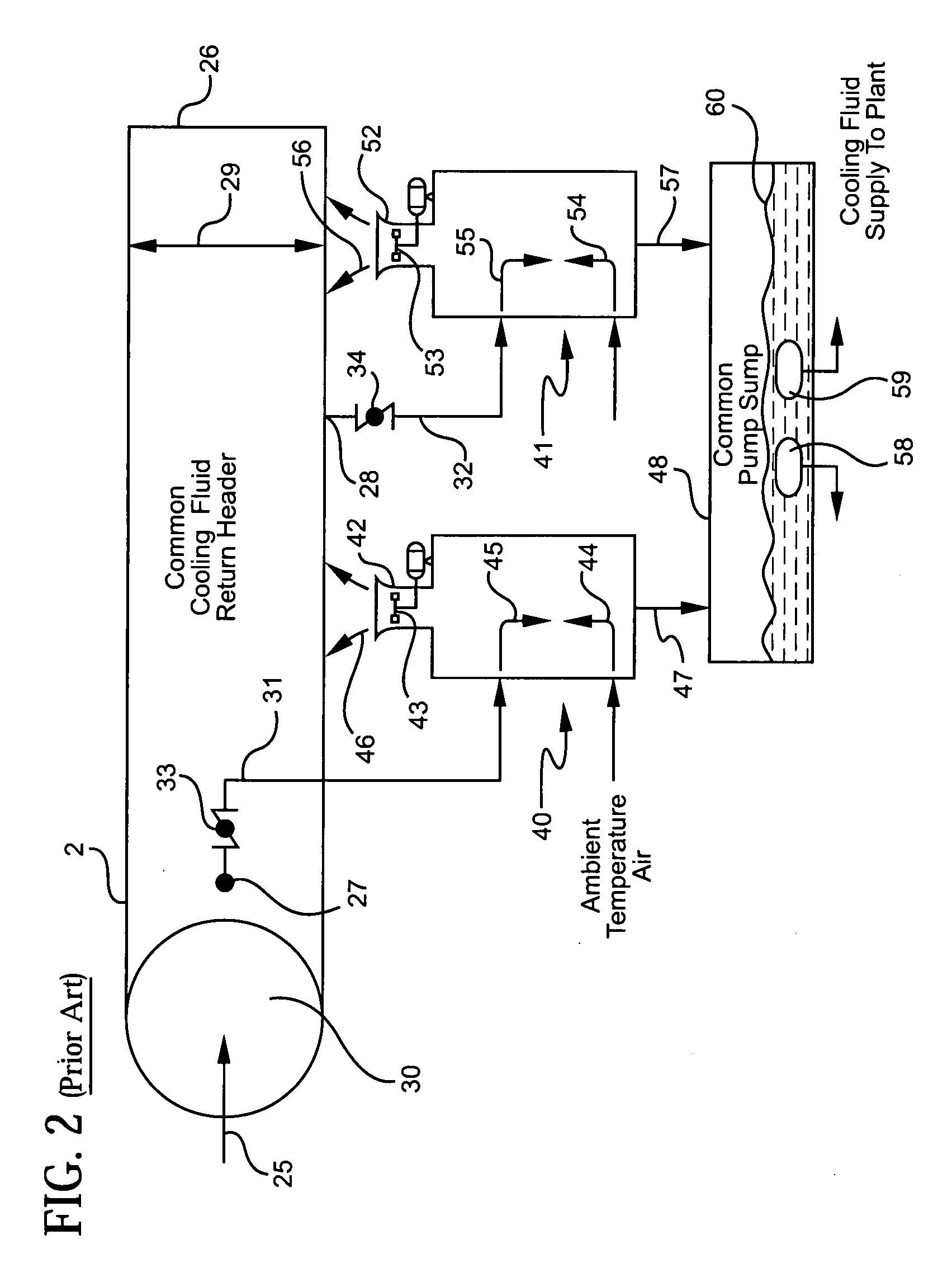
[0026]FIG. 1 shows a production plant 1 that carries a common header conduit 2 that returns heated cooling water to a cooling tower complex 3. Complex 3 is composed of 5 contiguous cooling cel...


PUM

PropertyMeasurementUnit
Areaaaaaaaaaaa
Levelaaaaaaaaaa
Elevationaaaaaaaaaa

Abstract

In a gravity fed cooling tower liquid return system having a common header with a plurality of valved sub-headers, a distributive control system, risers on the sub-headers, and sensor / transmitters on the risers, some of the sensor / transmitters controlling the valves on their respective sub-headers, sensing the liquid level in each of the sub-headers, comparing the sensed liquid levels in the distributive control system, and controlling the liquid levels in the sub-headers in response to the sensed liquid levels.

Description

BACKGROUND OF THE INVENTION[0001]1. Field of the Invention[0002]This invention relates to the operation of a cooling fluid system for a production plant wherein a gravity-drained cooling fluid return header system is employed to feed a cooling tower complex.[0003]More particularly, this invention relates to the operation of a gravity drained cooling fluid return system for a multi-cell cooling tower complex which return system provides a uniform flow of hot cooling fluid to each cooling cell of that complex.[0004]This invention is especially applicable to cooling fluid return systems that employ a single return header, which header feeds multiple return sub-headers wherein each sub-header feeds returned hot cooling fluid to an individual cooling cell in a multi-cell cooling tower complex.[0005]2. Description of the Prior Art[0006]For sake of clarity and brevity, this invention will be described in relation to a polyethylene production plant that uses an exothermic process for formin...

Claims


Application Information

Patent Timeline
IPC IPC(8): F28F27/00
CPCF28F27/003Y10S261/11Y10S165/90Y10T137/7287
Inventor SHIELD, DAVID B.
Owner EQUSR CHEM LP
Learn More