
Magnetic particle imaging equipment

A technology of magnetic particle imaging and equipment, which is applied in the field of medical imaging, can solve problems such as difficulty in realization, large power consumption, movement hysteresis and delay in the free zone of the magnetic field, and achieve relaxation effects, high timeliness, equipment scale and power consumption Reduced effect

Pending Publication Date: 2022-04-29
西安天策智脑电子科技有限公司
View PDF0 Cites 0 Cited by
  • Summary
  • Abstract
  • Description
  • Claims
  • Application Information

AI Technical Summary

Problems solved by technology

[0005] (1), high power consumption: the existing magnetic particle imaging equipment forms a magnetic field free area (point or line) in the middle of the selection field by constructing the selection field and the focus field, and moves the magnetic field free area in the focus field, in order to improve the image Resolution requires that the free point of the magnetic field is small enough, and the free line of the magnetic field is thin enough, so a large power consumption device is needed to generate a large enough current and a large gradient magnetic field
[0006] (2) Low spatial resolution: the image resolution of current medical imaging scanning technology can basically reach 0.5mm, while the existing magnetic particle imaging technology can only reach 5mm in the field of view of 20cm
[0007] (3) Blurred reconstructed image: The relaxation effect of magnetic particles causes hysteresis and delay in the movement of the free zone of the magnetic field, resulting in blurred reconstructed images
[0008] (4) Small field of view: The size of the imaging field of view of the existing magnetic particle imaging technology is determined by the composite magnetic field formed by the superimposition of the excitation field and the selection field. Usually, the ratio of the excitation magnetic field strength to the gradient of the selection field is used as the imaging field of view
At present, magnetic particle imaging is mainly used in mouse imaging. The imaging field of view is 1cm to 3cm, and the required excitation magnetic field strength is 15mT to 30mT. However, the scanning field of human body usually requires 20cm to 50cm, which requires a high excitation magnetic field strength. accomplish
[0009] (5) It is difficult to extend to clinical human body scanning: In order to meet the human body size magnetic particle imaging, a strong selection field and excitation field are required, resulting in a large power consumption, which is very difficult to implement
At the same time, the image spatial resolution of the existing magnetic particle imaging technology is too low or the field of view is too small, which is difficult to meet the requirements of clinical diagnosis
All existing magnetic particle imaging techniques are difficult to scale to clinical body scanning

Method used


Image

  • Magnetic particle imaging equipment
  • Magnetic particle imaging equipment
  • Magnetic particle imaging equipment

Examples


Embodiment 1

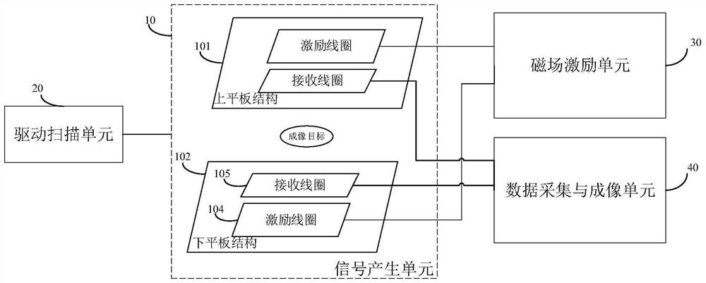
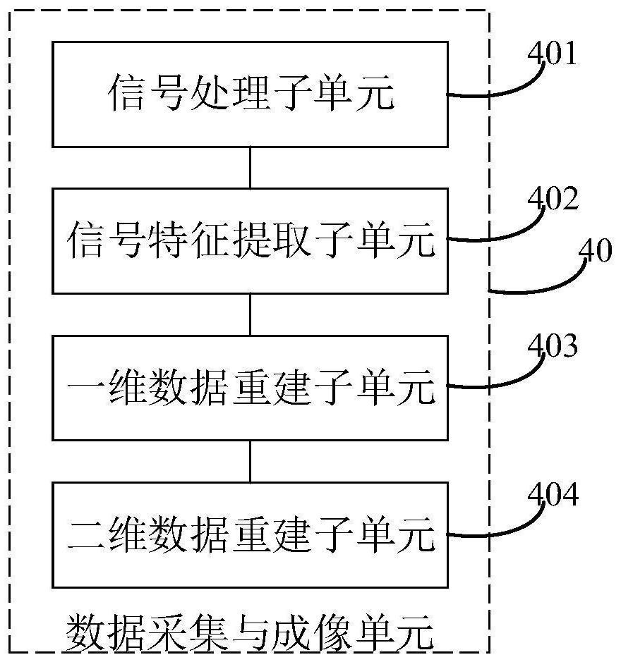
[0037] In order to solve the problems of high power consumption, low spatial resolution, blurred reconstructed image, small field of view and difficulty in extending to clinical human body scanning in the existing magnetic particle imaging equipment, please refer to figure 1 , the embodiment of the present invention proposes a magnetic particle imaging device, including: a signal generation unit 10, a drive scanning unit 20, a magnetic field excitation unit 30, and a data acquisition and imaging unit 40, wherein,

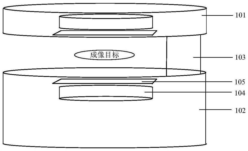
[0038] The signal generation unit 10 is used to generate an induced voltage signal under the action of a nonlinear and non-uniform excitation magnetic field; the signal generation unit 10 includes an upper plate structure 101 and a lower plate structure 102 opposite to each other, and the imaging target is located on the upper plate structure 101 and the lower plate structure 102. Between the lower plate structures 102; the upper plate structure 101 and the lower pla...


PUM


Abstract

The invention discloses a magnetic particle imaging device, which comprises a signal generation unit used for generating an induced voltage signal under the action of a non-linear and non-uniform excitation magnetic field; the signal generating unit comprises an upper flat plate and a lower flat plate which are opposite in position. Exciting coils and receiving coils are arranged in the upper flat plate and the lower flat plate; the driving scanning unit drives the exciting coil and the receiving coil in the upper flat plate and the lower flat plate to do circular motion; the circular motion directions are opposite; each circular motion comprises a plurality of data acquisition points; the magnetic field excitation unit is used for applying homodromous alternating current to the excitation coils in the upper flat plate and the lower flat plate at each data acquisition point in each circular motion to generate a nonlinear and non-uniform excitation magnetic field; and the data acquisition and imaging unit is used for acquiring induced voltage signals generated on the receiving coils of the upper flat plate and the lower flat plate at each data acquisition point in each circular motion so as to obtain target acquisition data and perform magnetic particle imaging. According to the invention, low-power-consumption, large-view and high-resolution magnetic particle imaging is realized.

Description

technical field [0001] The invention belongs to the technical field of medical imaging, and in particular relates to a magnetic particle imaging device. Background technique [0002] In clinical diagnosis and detection, how to accurately and objectively locate tumors and other targets has always been an international research hotspot and challenging issue. Existing medical imaging technologies such as computer tomography (Computed Tomography, referred to as CT), magnetic resonance imaging (Magnetic Resonance Imaging, referred to as MRI), single-photon emission computed tomography (Single-Photon Emission Computed Tomography, referred to as SPECT) and other methods are all There are problems such as great harm, poor positioning, and low precision. In recent years, a new tracer-based imaging method, Magnetic Particle Imaging (MPI for short), has been proposed. [0003] Using tomographic imaging technology, MPI can accurately locate tumors or other targets by detecting the spa...

Claims


Application Information

Patent Timeline
Patent Type & Authority Applications(China)
IPC IPC(8): A61B5/0515
CPCA61B5/0515
Inventor 李檀平贾广胡凯黄力宇苗启广张艺飞
Owner 西安天策智脑电子科技有限公司
Learn More