
Magnetic particle imaging equipment without magnetic field free area

A magnetic particle imaging, free technology, applied in the field of magnetic particle imaging, which can solve the problems of delay, large scale and power consumption of imaging equipment, and inability to do so.

Pending Publication Date: 2022-05-06
石文
View PDF0 Cites 0 Cited by
  • Summary
  • Abstract
  • Description
  • Claims
  • Application Information

AI Technical Summary

Problems solved by technology

[0007] However, changing the position of the magnetic field free zone requires an additional focusing field or driving field, which makes the scale and power consumption of the entire imaging device relatively large
Moreover, in order to improve the resolution of the imaging image, the free area of ​​the magnetic field needs to be small enough, which requires a high-power device to generate a large enough current to generate a large gradient field; in addition, the smaller the free area of ​​the magnetic field, the imaging of the entire imaging target More points need to be collected, resulting in longer scanning time, and the increase of scanning time increases the relaxation effect of magnetic particles, which makes the movement of the free zone of the magnetic field lag and delay, causing the final imaging image to become blurred
Due to the above factors, the existing magnetic particle imaging technology can only achieve an image resolution of 5mm at a field of view of 20cm, and it can only be applied to the imaging of a mouse-sized target at present.
However, the scanning field of view for imaging human targets usually needs to be 20cm to 50cm, which cannot be achieved by the existing magnetic particle imaging technology.

Method used


Image

  • Magnetic particle imaging equipment without magnetic field free area
  • Magnetic particle imaging equipment without magnetic field free area
  • Magnetic particle imaging equipment without magnetic field free area

Examples


Embodiment Construction

[0056] The present invention will be described in further detail below in conjunction with specific examples, but the embodiments of the present invention are not limited thereto.

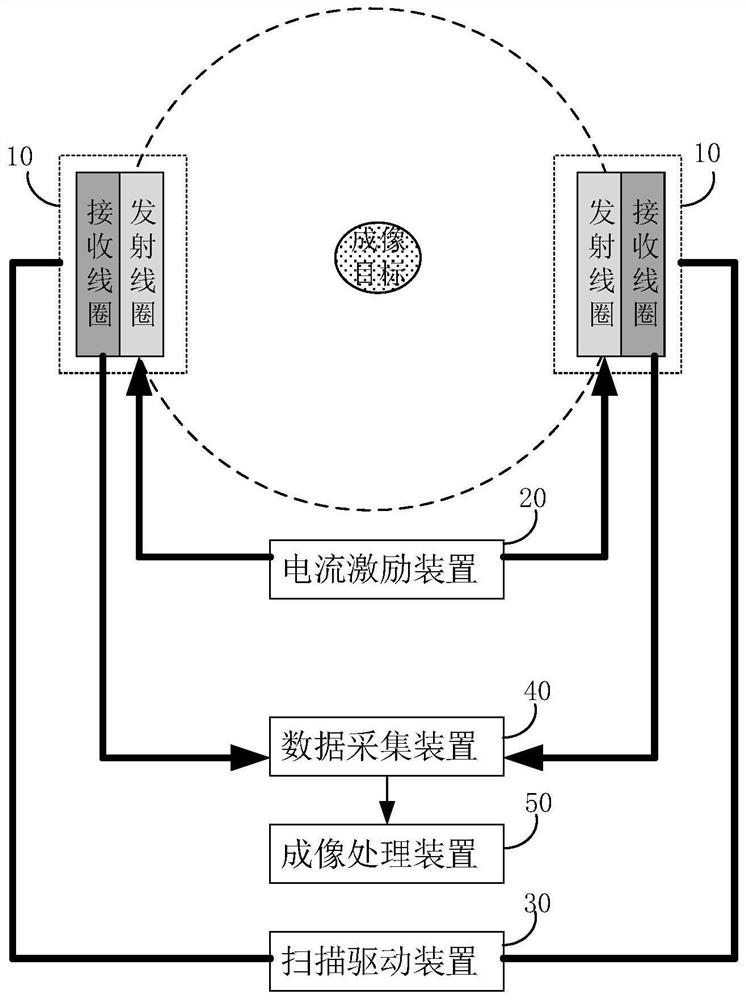
[0057] In order to solve the problems of high power consumption, small field of view, and low scanning efficiency in the existing magnetic particle imaging technology, so that the magnetic particle imaging technology can be applied to the scanning imaging of the human body, the embodiment of the present invention provides a magnetic field free zone magnetic particle imaging equipment. It should be noted that the imaging target in the embodiment of the present invention is not limited to the human body, any object whose internal structure can be probed by means of magnetic particle imaging can be used as the imaging target in the embodiment of the present invention.

[0058] see figure 1 As shown, the magnetic particle imaging equipment without magnetic field free zone provided by the implementatio...


PUM


Abstract

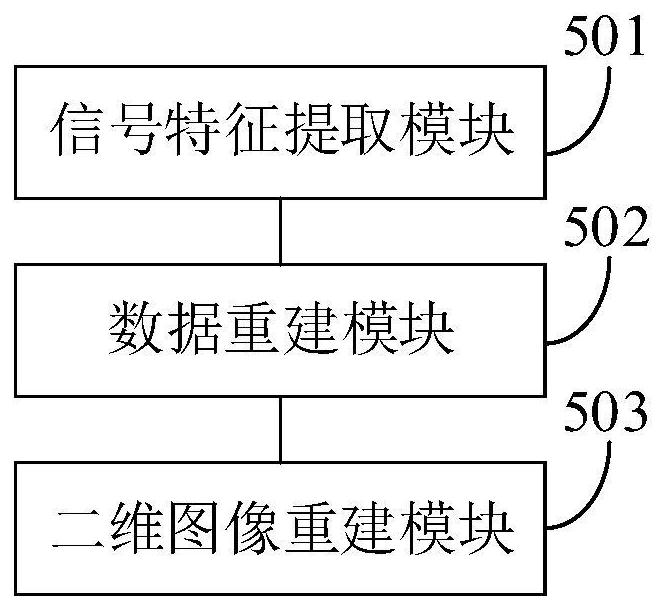
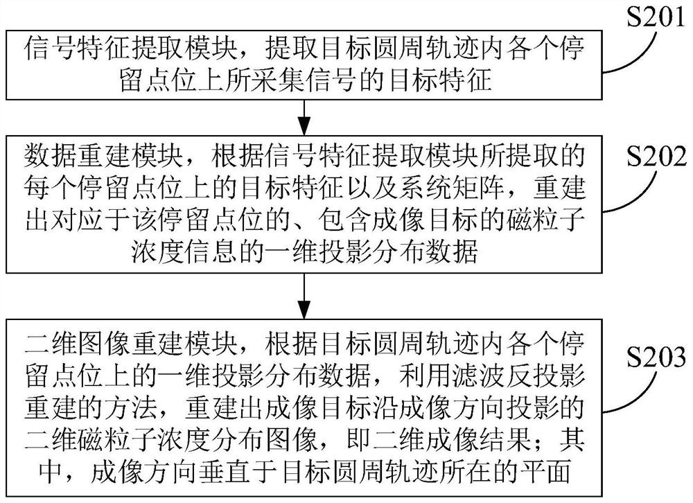
The invention discloses magnetic particle imaging equipment without a magnetic field free area. The magnetic particle imaging equipment comprises a pair of transmitting coils, a pair of receiving coils, a current excitation device, a scanning driving device, a data acquisition device and an imaging processing device, the scanning driving device drives the coil to move along a circumferential track; each circumferential track comprises a plurality of staying point positions; the current excitation device is used for applying current to the transmitting coils when the coils stop at the stop point positions, the current amplitude in one transmitting coil is gradually increased, the current amplitude in the other transmitting coil is synchronously reduced, and each time the current amplitude is adjusted, the current amplitude goes through a half cosine oscillation period; the data acquisition device acquires the induced voltage of the receiving coil in each half cosine oscillation period as an acquired signal; and the imaging processing device carries out magnetic particle concentration spatial distribution imaging on the imaging target according to the target characteristics of the signals acquired at the staying point positions in the circumferential track. The method has a relatively large imaging view field and relatively high image spatial resolution, and can be used for human body clinical scanning imaging.

Description

technical field [0001] The invention belongs to the technical field of magnetic particle imaging, and in particular relates to a magnetic particle imaging device without a magnetic field free zone. Background technique [0002] Clinical medical imaging technology is mainly divided into two categories: one is structural imaging, and the other is functional imaging. Among them, structural imaging mainly shows the internal organs and tissue structures of the human body, and the imaging methods include ultrasound, magnetic resonance imaging, CT (Computed Tomography, electronic computer tomography) and the like. Functional imaging is to display the functions of blood vessels, organs, tissues and cells. Imaging methods include DSA (Digital Subtraction Angiography, digital subtraction angiography), PET (Positron Emission Computed Tomography, positron emission computed tomography), SPECT ( Single Photon Emission Computed Tomography, single photon emission computed tomography) and C...

Claims


Application Information

Patent Timeline
IPC IPC(8): A61B5/0515A61B5/00G01R33/12
CPCA61B5/0515A61B5/72G01R33/1276
Inventor 石文
Owner 石文
Learn More