Easily-adjustable durable welding contact tube and method
A kind of contact tip, durable technology, applied in the direction of electrode accessories, welding rod characteristics, etc., can solve problems such as pores, obstructions, lack of protective gas protection in the molten pool, etc., to reduce high temperature softening phenomenon, improve welding quality, and high adjustment accuracy. Effect
- Summary
- Abstract
- Description
- Claims
- Application Information
AI Technical Summary
Problems solved by technology
Method used
Image
Examples
Embodiment 1
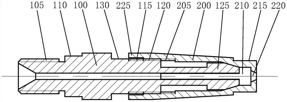
[0035] Example 1: figure 1 is a structural diagram of this embodiment. This figure shows the state of the contact tip when it is not worn, and the contact tip is composed of a main body 100 and an adjustment sleeve 200 . The main body 100 is made of materials with good electrical conductivity, such as copper, silver, aluminum, graphene and the like. The adjustment sleeve 200 can be made of various metal materials. When selecting materials, it is best to choose materials with a lower coefficient of thermal expansion than the main body 100. The materials should also have certain anti-splash properties. If materials with poor anti-splash properties are used, the It has anti-splash treatment. But the best solution is ceramics, because ceramics can not only play a good anti-splash effect on the welding of any material, but also have a low thermal expansion coefficient and have good stability in connection with the main body 100 . The rear end of the main body 100 is the connecti...
Embodiment 2
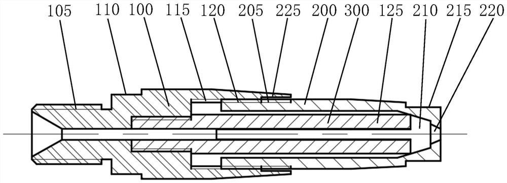
[0039] Example 2: figure 2 is a structural diagram of this embodiment. The main body thread 115 in this embodiment is an internal thread, and the adjusting sleeve thread is an external thread. In this embodiment, the front end of the conductive block 125 has no taper, but in order to achieve the purpose of drawing the conductive block 125 inward, a taper is provided on the adjustment hole 210 , so the adjustment hole 210 is conical. For the convenience of manufacture, the conductive block 125 is arranged on the core body 300, so this structure can make the conductive block 125 very long, and the cross-sectional size of the conductive block 125 can be appropriately increased without increasing its rigidity. The core body 300 and the main body 100 have a cylindrical hole for the welding wire to pass through, and the core body 300 is connected to the main body 100. The connection between the core body 300 and the main body 100 should be tight, and ensure that there is enough co...
Embodiment 3
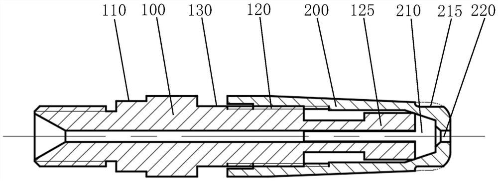
[0040] Embodiment 3: In this embodiment, the adjusting sleeve 200 adopts an internal thread, and the adjusting hole 210 is a conical hole, such as image 3 shown. The structure of the conductive block 125 can be handled flexibly as long as the three prerequisites described in Embodiment 1 are met. The front end of the guide hole 220 is a cylindrical hole, the rear end is a conical hole, and the front end of the adjustment sleeve is a rounded structure. The purpose is to reduce the area of the head plane, which can effectively reduce the adhesion of splashes. In addition, optimizing the surface roughness of the adjusting sleeve 200 , especially the head, to make it smoother can also reduce splash adhesion. Although the ceramic adjustment sleeve has the characteristics of low thermal expansion coefficient, its toughness is not as good as the copper adjustment sleeve. The adjustment sleeve 200 is made of ceramic or copper, aluminum and other metals, and it needs to be flexibly...
PUM
 Abstract
Description
Claims
Application Information
 - R&D
- Intellectual Property
- Life Sciences
- Materials
- Tech Scout
- Unparalleled Data Quality
- Higher Quality Content
- 60% Fewer Hallucinations
Browse by: Latest US Patents, China's latest patents, Technical Efficacy Thesaurus, Application Domain, Technology Topic, Popular Technical Reports.
© 2025 PatSnap. All rights reserved.Legal|Privacy policy|Modern Slavery Act Transparency Statement|Sitemap|About US| Contact US: help@patsnap.com


