Motion track planning method for mechanical arm servo tumbling satellite butt joint circular ring

A technology of motion trajectory and manipulator, which is applied in the direction of manipulator, program control manipulator, manufacturing tools, etc., can solve the problems of inability to complete the servo manipulator work space within the specified time, drift of the end track of the manipulator, and inability to lock, etc.

Active Publication Date: 2022-04-29
HARBIN INST OF TECH
View PDF6 Cites 0 Cited by
  • Summary
  • Abstract
  • Description
  • Claims
  • Application Information

AI Technical Summary

Problems solved by technology

[0004] The purpose of the present invention is to solve the problem that the trajectory of the end of the mechanical arm drifts on the docking ring during the tracking process due to the inability to lock the capture point of the docking ring of the failed satellite when the existing robotic arm servo planning technology is applied to the failed satellite. The completion of the servo within the specified time causes the target to drift out of the working space of the manipulator, and a motion trajectory planning method for the manipulator servo tumbling satellite docking ring is proposed

Method used


Image

  • Motion track planning method for mechanical arm servo tumbling satellite butt joint circular ring
  • Motion track planning method for mechanical arm servo tumbling satellite butt joint circular ring
  • Motion track planning method for mechanical arm servo tumbling satellite butt joint circular ring

Examples


specific Embodiment approach 1

[0027] Specific implementation mode one: combine Figure 1-2 In this embodiment, a method for planning a motion trajectory of a robotic arm servo tumbling satellite docking ring, the specific process is as follows:

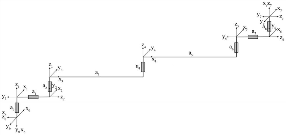
[0028] Step 1. Obtain the pose matrix of the base system of the manipulator relative to the end tool system according to the joint angle information fed back by the joint position sensor of the manipulator in real time e T b ; The joint coordinate system of the manipulator is as follows figure 1 As shown, the corresponding DH parameter table is shown in Table 1;

[0029]

[0030] Among them, θ is the vector of 7 joint angles, l is the length parameter of the connecting rod of the manipulator, which is the connecting rod offset distance d i the value of b T 0 is a constant matrix, e T b Indicates the pose matrix from the base system of the manipulator to the end tool system, e is the end tool system, b is the base system of the manipulator, e no b , ...

Embodiment

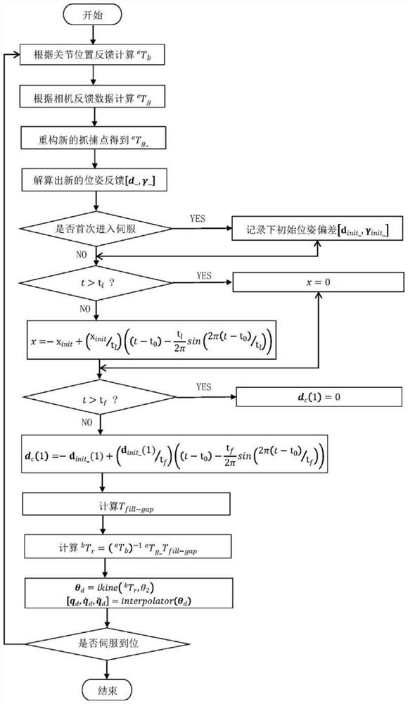
[0097] For the effectiveness of the present invention, the following combination image 3 To Fig. 6, the technical solution of the present invention is further described, using computer simulation.

[0098] Build a computer simulation platform, start the servo, the specific implementation steps are as attached image 3 As shown, the following operations are performed in each planning cycle:

[0099] [Step S1] Calculation based on joint angle feedback e T b ;

[0100] [Step S2] Calculation based on joint angle feedback e T g ;

[0101] [Step S3] The radius of the target docking ring is 813.25mm, reconstruct the new capture point, and calculate e T g_ ;

[0102] [Step S4] From e T g_ Solve the new pose feedback [d_, γ_];

[0103] [Step S5] Judging whether to enter the servo for the first time, if it is the first time to enter the servo, record the initial pose deviation [d init_ , gamma init_ ], otherwise go directly to the next step;

[0104] [Step S6] Judging wh...


PUM


Abstract

The invention discloses a motion track planning method for a mechanical arm servo tumbling satellite docking ring, and relates to the field of track planning. The method aims at solving the problem that when an existing mechanical arm servo planning technology is applied to a failed satellite, a capture point of a docking ring of the failed satellite cannot be locked, and consequently the tail end track of a mechanical arm drifts on the docking ring in the tracking process. The method comprises the steps that a pose matrix eTb of a mechanical arm base system relative to a tail end tool system is obtained; obtaining a pose matrix eTg of the docking ring capture point coordinate system relative to the end tool system; the attitude information of a mechanical arm base system in the eTb is utilized, the tail end tool system serves as a reference coordinate system, the eTg is reconstructed, and the pose information [d, gamma] of the reconstructed docking ring capture point coordinate system relative to the tail end tool system is obtained; planning an expected path at the tail end of the mechanical arm based on a trigonometric function, so that [d, gamma] is converged to a capture tolerance within a preset time; and obtaining the subdivided joint track of the mechanical arm by using the expected path at the tail end of the mechanical arm. The method is used for planning the motion trail of the servo butt joint circular ring of the mechanical arm.

Description

technical field [0001] The invention relates to the field of trajectory planning, in particular to a motion trajectory planning method for a robot arm servo-tumbling satellite docking ring. Background technique [0002] The failed satellites have no cooperative markers. In order to capture such satellites, a hand-eye camera is installed at the end of the robotic arm, and the relative pose between the end tool system and the target is obtained by measuring typical features on the satellite. Common features of failed satellites include docking rings, sail brackets, antennas, etc. Among them, the docking ring has sufficient strength and can be used as the grasping interface of the end tool. Therefore, the docking ring is the most ideal servo target and capture interface for the failed satellite. In addition, the failure target is generally in the rolling state of rotation-coupled nutation. Capturing this type of target poses a huge challenge to the servo planning technology of...

Claims


Application Information

Patent Timeline
Patent Type & Authority Applications(China)
IPC IPC(8): B25J9/16
CPCB25J9/1664B25J9/1697
Inventor 杨国财崔士鹏纪军红李志奇倪风雷金明河刘宏
Owner HARBIN INST OF TECH
Why Eureka
Try Eureka