Intelligent lining trolley for tunnel

A lining trolley, intelligent technology, applied in the direction of tunnel lining, tunnel, wellbore lining, etc., can solve the problems of increasing the risk factor, generating cracks, falling off fragments, etc., to achieve the effect of improving the breadth of application, reducing manufacturing costs, and improving lining efficiency.

Pending Publication Date: 2022-04-29
中交二公局第四工程有限公司
View PDF0 Cites 0 Cited by
  • Summary
  • Abstract
  • Description
  • Claims
  • Application Information

AI Technical Summary

Problems solved by technology

Most of the existing tunnel lining trolleys are designed in one-to-one correspondence with the tunnel, which leads to slow production and preparation of lining trolleys, especially when selecting lining trolleys for tunnels with the same shape and different sizes, if the Re-preparing the lining trolley will make the tunnel lining efficiency low, and some lining trolleys that can be adjusted in size, the adjusted support strength, support force direction and support point, etc. are all the same as the optimal support state of the initial design. Even though it can adapt to tunnels of various sizes, the adjusted structure is difficult to achieve the best structural shape, which leads to an increase in the risk factor during the lining process, and after the grout solidifies, the formwork and solidification When the surfaces are separated from each other, it often causes the surface of the solidified wall to be pulled and torn by the formwork, falling off fragments and even cracks

Method used


Image

  • Intelligent lining trolley for tunnel
  • Intelligent lining trolley for tunnel
  • Intelligent lining trolley for tunnel

Examples


Embodiment Construction

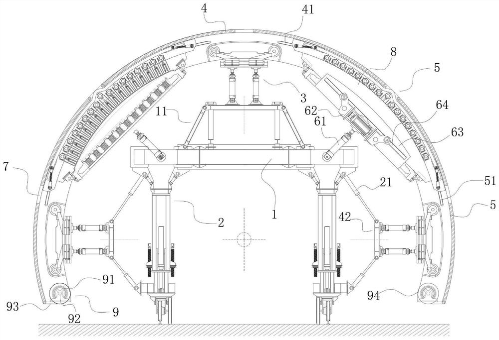
[0035] refer to Figure 1-5 , the present invention provides a technical solution: a tunnel intelligent lining trolley, which includes:

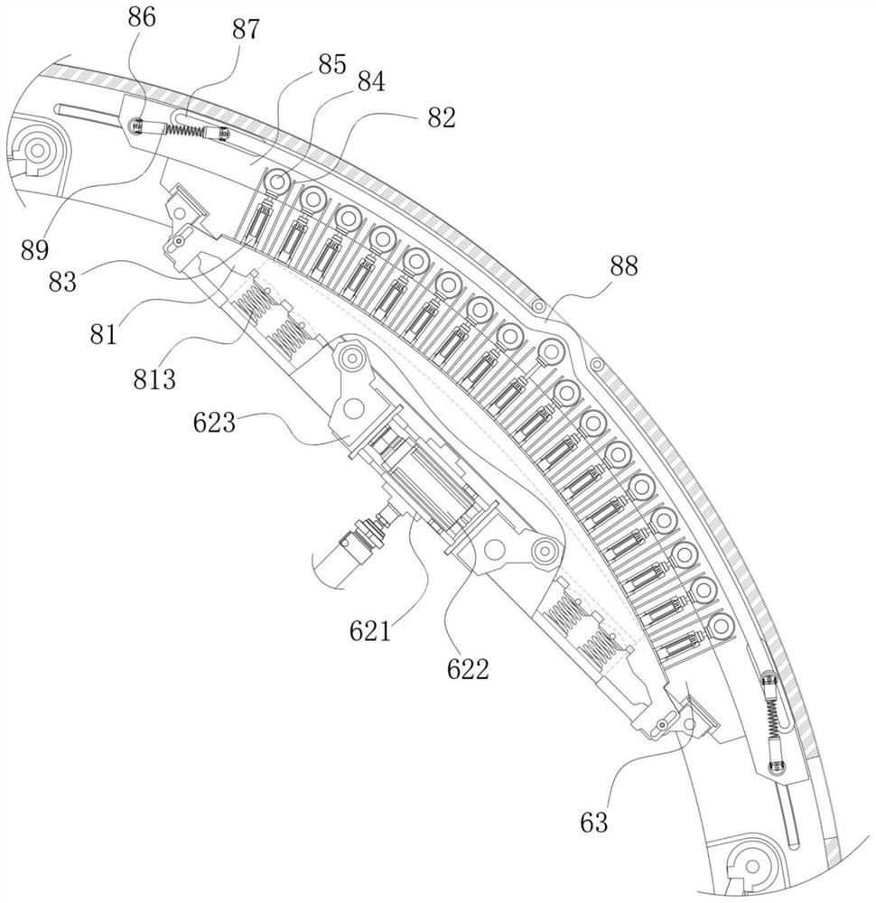
[0036] Crossbeam frame 1, multiple groups are arranged parallel to the front and rear of the same level, and are fixed. A trapezoidal support frame 11 is installed in the center of the upper side of each group of horizontal frame 1, and a vertically arranged liftable walking frame 2 is installed on the lower side near the left and right ends. The left and right ends are symmetrically installed with an upwardly inclined 45° mold expanding device 6, and the outer boundary surface of the mold expanding device 6 is an arc-shaped curved surface, and the outer side of the liftable walking frame 2 is hinged with a lifting rod 21 at the upper and lower ends;

[0037] The hydraulic jacking frame 3 is configured in multiple groups, and is installed vertically on the upper end of the corresponding trapezoidal support frame 11, and installed horizontall...


PUM


Abstract

The invention discloses a tunnel intelligent lining trolley which comprises a plurality of sets of cross beam frames which are arranged on the same horizontal plane in a front-back parallel mode and fixed, a trapezoid bearing frame is installed in the center of the upper side of each set of cross beam frames, lifting walking frames which are longitudinally arranged are installed at the positions, close to the left end and the right end, of the lower side of each set of cross beam frames, and formwork expanding devices which incline upwards by 45 degrees are symmetrically installed at the left end and the right end. Lifting rods are hinged to the outer side of the liftable walking frame close to the upper end and the lower end respectively; the hydraulic jacking frames are arranged into multiple groups, are respectively and vertically mounted at the upper ends of the corresponding trapezoidal supporting frames, and are transversely mounted at the output ends of the lifting rods above and below the corresponding sides; the top template is arranged corresponding to the vertical hydraulic jacking frame; and the side formworks are installed corresponding to the transverse hydraulic jacking frame, the side formworks, the top formwork and the formwork expanding device are arranged in a concentric circle structure form, film covering assemblies are correspondingly installed at the lower ends of the side formworks on the left side and the right side in a matched mode, and grouting holes are formed in the top formwork and the side formworks.

Description

technical field [0001] The invention relates to the technical field of lining trolleys, in particular to an intelligent lining trolley for tunnels. Background technique [0002] The tunnel lining trolley is special equipment that must be used in the secondary lining of the tunnel construction process, and is used for the concrete lining construction of the inner wall of the tunnel. Most of the existing tunnel lining trolleys are designed in one-to-one correspondence with the tunnel, which leads to slow production and preparation of lining trolleys, especially when selecting lining trolleys for tunnels with the same shape and different sizes, if the Re-preparing the lining trolley will make the tunnel lining efficiency low, and some lining trolleys that can be adjusted in size, the adjusted support strength, support force direction and support point, etc. are all the same as the optimal support state of the initial design. Even though it can adapt to tunnels of various sizes...

Claims


Application Information

Patent Timeline
Patent Type & Authority Applications(China)
IPC IPC(8): E21D11/10E21D11/40
CPCE21D11/102E21D11/105E21D11/40
Inventor 杨关飞贺正伟司纲罗虎杨国防黄晓龙王生玉
Owner 中交二公局第四工程有限公司
Why Eureka
Try Eureka