
Circuit capable of being used for static acceleration measurement and measurement device

A technology of acceleration measurement and accelerometer, which is applied in the direction of acceleration measurement, measurement device, speed/acceleration/shock measurement, etc. by using inertial force, and can solve the problem of anti-surge or static electricity that cannot guarantee normal work, poor sensitivity consistency, and cumbersome assembly process To achieve excellent temperature stability and parameter consistency, reduce assembly man-hours, and save assembly links

Pending Publication Date: 2022-04-29
XIAMEN NIELL ELECTRONICS
View PDF1 Cites 0 Cited by
  • Summary
  • Abstract
  • Description
  • Claims
  • Application Information

AI Technical Summary

Problems solved by technology

The acceleration sensor of the IEPE interface uses a constant current source for power supply, and at the same time outputs a voltage signal on the power supply circuit, that is, only two signal lines are needed to realize power supply and signal output. The IEPE interface is widely used in the field of vibration and acceleration measurement, but There are still the following defects: 1. The sensitive unit is a piezoelectric acceleration sensor of piezoelectric ceramics or piezoelectric crystals, which can only be used to measure dynamic acceleration, and cannot be used to measure static acceleration, such as gravitational acceleration
2. Piezoelectric acceleration sensors are affected by piezoelectric ceramics or piezoelectric crystal materials and sensor structure types, and their stability caused by temperature is poor
3. The assembly of the piezoelectric acceleration sensor involves brackets, mass blocks, ceramics, etc. The assembly process is cumbersome and requires a lot of man-hours
4. Affected by materials, assembly, etc., its sensitivity consistency is poor, and it needs to be adjusted by a charge amplification circuit
5. The lower limit of the excitation current of most piezoelectric acceleration sensors is 2mA, and the upper limit is generally 10mA or 20mA. It is often difficult to design low-current excitation
Although its acceleration sensor can measure static acceleration and is compatible with the IEPE interface, which simplifies the wiring and can make up for the lack of static response of the existing IEPE sensor, the circuit is relatively complicated, and there are no anti-reverse, anti-surge or static electricity measures and cannot be guaranteed It can still work normally under 2mA external excitation current

Method used


Image

  • Circuit capable of being used for static acceleration measurement and measurement device
  • Circuit capable of being used for static acceleration measurement and measurement device
  • Circuit capable of being used for static acceleration measurement and measurement device

Examples


Embodiment 1

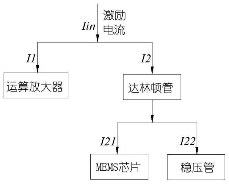
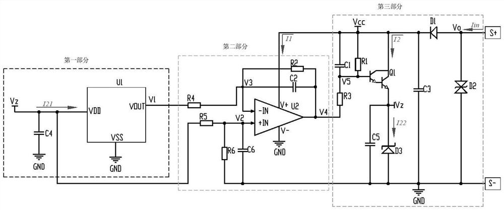
[0031] Such as figure 1 As shown, the present embodiment provides a circuit that can be used for static acceleration measurement, including a MEMS accelerometer, a DC amplifier circuit unit and a power supply processing circuit unit; the output end of the MEMS accelerometer is connected to the DC amplifier circuit unit, and the The DC amplification circuit unit is connected to the power supply processing circuit unit, and the power supply processing circuit unit receives power from a constant current source, and supplies power to the MEMS accelerometer and the DC amplification unit respectively;

[0032] Such as figure 2 As shown, wherein, the overall working principle of the circuit: the MEMS accelerometer converts the external acceleration signal into a corresponding voltage signal output, and the DC amplifier circuit unit amplifies and adjusts the voltage signal output by the MEMS accelerometer, and performs The low-pass filter attenuates the out-of-band high frequency, t...

Embodiment 2

[0052] Such as Figure 7 As shown, this embodiment provides a static acceleration measurement device, which has the measurement circuit as described in the first embodiment. Since the device introduced in the second embodiment of the present invention includes the circuit implementing the first embodiment of the present invention, based on the circuit introduced in the first embodiment of the present invention, those skilled in the art can understand the specific structure and deformation of the device, so here No longer.

[0053] The technical solutions provided in the embodiments of the present application have at least the following technical effects or advantages: Optimizing the current distribution of the MEMS accelerometer through the DC amplifier circuit unit and the power supply processing circuit unit can greatly reduce the excitation current, and the minimum can reach 2mA. In addition, it also has the following advantages:

[0054] 1. Two-wire system is adopted, th...


PUM


Abstract

The invention provides a circuit capable of being used for static acceleration measurement and a measurement device. The measurement circuit comprises an MEMS accelerometer, a direct current amplification circuit unit and a power supply processing circuit unit. The MEMS accelerometer converts an external acceleration signal into a corresponding voltage signal and outputs the voltage signal, the direct current amplification circuit unit amplifies and adjusts the voltage signal output by the MEMS accelerometer, performs low-pass filtering and attenuates out-of-band high frequency, and the power supply processing circuit unit generates an output quiescent working point voltage and outputs the quiescent working point voltage. Meanwhile, the filtered voltage signal is further amplified; a final output voltage Vo is obtained; therefore, the maximum value of the excitation current can be 2mA by reasonably distributing the current. The static acceleration sensor not only can measure the static acceleration and is compatible with an IEPE interface, but also can ensure that the static acceleration sensor can still work normally under 2mA external excitation current, thereby being compatible with the excitation current range of most existing piezoelectric acceleration sensors.

Description

technical field [0001] The invention relates to the field of acceleration measurement circuits, in particular to a circuit and a measurement device that can be used for static acceleration measurement. Background technique [0002] Vibration measurements are required on railway bogies, aero engines or other internal combustion powered machinery. At present, the sensitive unit of the acceleration sensor used to measure the vibration mostly adopts the piezoelectric effect type piezoelectric ceramic or piezoelectric crystal with the output of the electric charge with superior characteristics, and in order to reduce the number of cables, the standard piezoelectric integrated circuit interface ( integral electronic piezo electric, IEPE). The acceleration sensor of the IEPE interface uses a constant current source for power supply, and at the same time outputs a voltage signal on the power supply circuit, that is, only two signal lines are needed to realize power supply and signa...

Claims


Application Information

Patent Timeline
IPC IPC(8): G01P15/08G01P15/125
CPCG01P15/08G01P15/125
Inventor 陈昌鹏周富强谢刚蔡魏威翁新全许静玲柯银鸿刘瑞林
Owner XIAMEN NIELL ELECTRONICS
Learn More