Fuel cell membrane electrode, preparation method thereof and fuel cell
A fuel cell membrane and electrode technology, applied in the direction of fuel cells, battery electrodes, circuits, etc., can solve the problems of reducing the HOR reaction activity of the anode catalytic layer, reducing the overall performance of the battery, and damage to the membrane electrode, so as to ensure the electrical performance and improve the resistance. Polarity Reversal Ability, Effect of Boosting Performance and Durability
- Summary
- Abstract
- Description
- Claims
- Application Information
AI Technical Summary
Problems solved by technology
Method used
Image

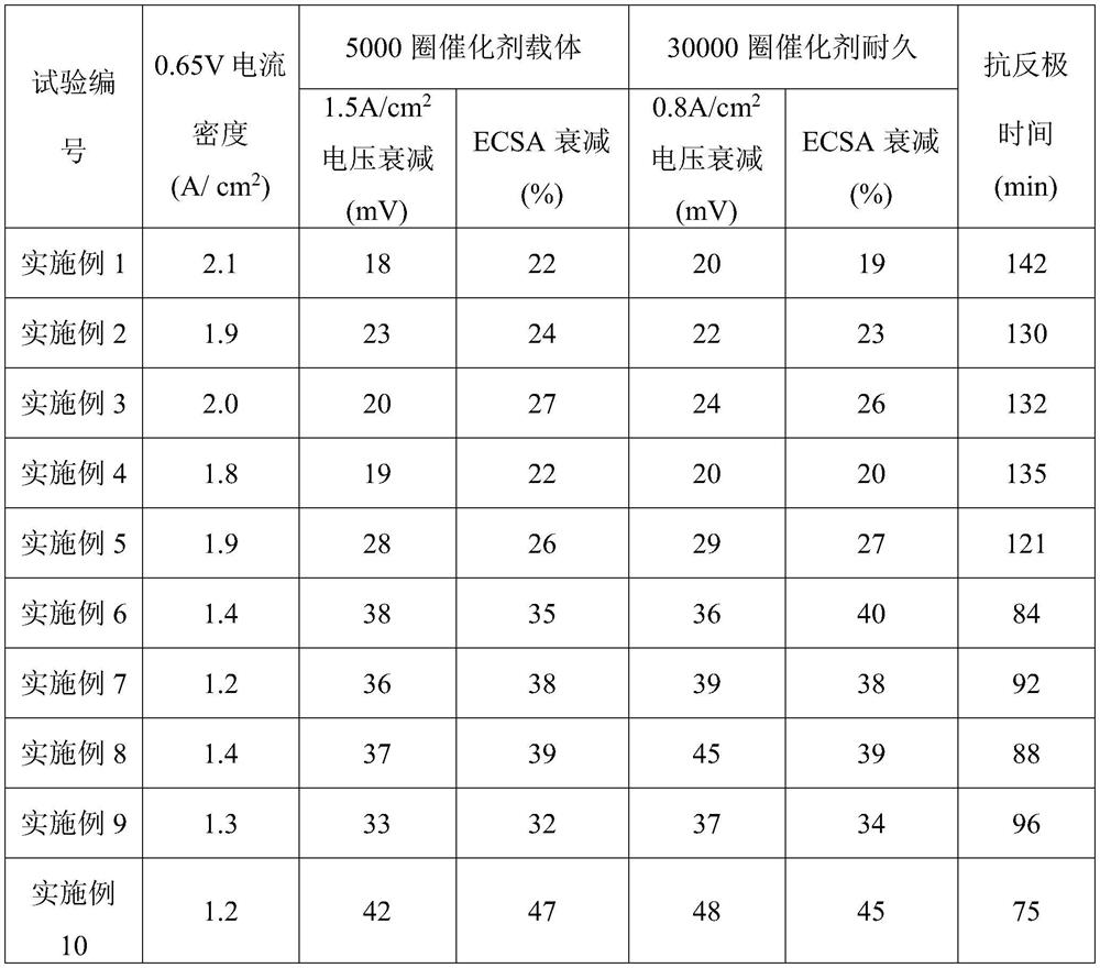
Examples
Embodiment 1
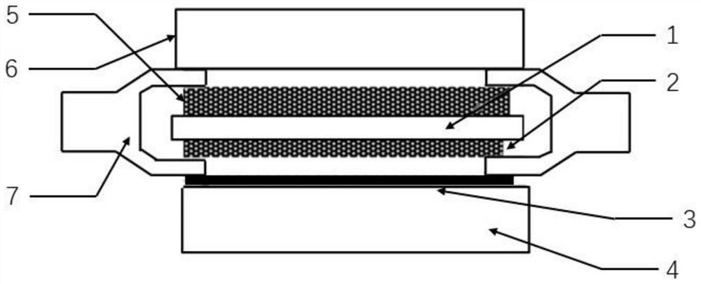
[0074] This embodiment provides a fuel cell membrane electrode, the structure schematic diagram is as follows figure 1 shown. The fuel cell membrane electrode includes an anode gas diffusion layer 6 , an anode first catalyst layer 2 , an anode second catalyst layer 3 , a proton membrane 1 , a cathode catalyst layer 4 , a cathode gas diffusion layer 5 and a sealing member 7 .
[0075] The thickness of the anode gas diffusion layer 6 is 240 μm, the thickness of the first catalytic layer 2 of the anode is 2 μm, the thickness of the second catalytic layer 3 of the anode is 0.8 μm, the thickness of the proton membrane 1 is 13 μm, and the thickness of the cathode catalytic layer 4 is The thickness of the cathode gas diffusion layer 5 is 200 μm.
[0076] The platinum loading of the anode first catalytic layer 2 is 0.08 mg / cm 2 , the catalyst of the anode second catalytic layer 3 is iridium oxide, and the platinum loading of the cathode catalytic layer 4 is 0.22 mg / cm 2 .
[0077]...
Embodiment 2
[0087] This embodiment provides a fuel cell membrane electrode, the structure schematic diagram is as follows figure 1 shown. The fuel cell membrane electrode includes an anode gas diffusion layer 6 , an anode first catalyst layer 2 , an anode second catalyst layer 3 , a proton membrane 1 , a cathode catalyst layer 4 , a cathode gas diffusion layer 5 and a sealing member 7 .
[0088] The thickness of the anode gas diffusion layer 6 is 220 μm, the thickness of the first catalytic layer 2 of the anode is 2 μm, the thickness of the second catalytic layer 3 of the anode is 0.6 μm, the thickness of the proton membrane 1 is 10 μm, and the thickness of the cathode catalytic layer 4 is 8 μm, and the thickness of the cathode gas diffusion layer 5 is 180 μm.
[0089] The platinum loading of the anode first catalytic layer 2 is 0.07 mg / cm 2 , the catalyst of the anode second catalytic layer 3 is iridium black, and the platinum loading of the cathode catalytic layer 4 is 0.15 mg / cm 2 ....
Embodiment 3
[0100] This embodiment provides a fuel cell membrane electrode, the structure schematic diagram is as follows figure 1 shown. The fuel cell membrane electrode includes an anode gas diffusion layer 6 , an anode first catalyst layer 2 , an anode second catalyst layer 3 , a proton membrane 1 , a cathode catalyst layer 4 , a cathode gas diffusion layer 5 and a sealing member 7 .
[0101] The thickness of the anode gas diffusion layer 6 is 260 μm, the thickness of the first catalytic layer 2 of the anode is 3.5 μm, the thickness of the second catalytic layer 3 of the anode is 0.9 μm, the thickness of the proton membrane 1 is 16 μm, and the thickness of the cathode catalytic layer 4 is The thickness of the cathode gas diffusion layer 5 is 220 μm.
[0102] The platinum loading of the first catalytic layer 2 of the anode is 0.09 mg / cm 2 , the catalyst of the anode second catalytic layer 3 is ruthenium, and the platinum loading of the cathode catalytic layer 4 is 0.3 mg / cm 2 .
[0...
PUM
| Property | Measurement | Unit |
|---|---|---|
| thickness | aaaaa | aaaaa |
| thickness | aaaaa | aaaaa |
| thickness | aaaaa | aaaaa |
Abstract
Description
Claims
Application Information