
Broadband directional coupler based on bent line structure equivalent circuit

A technology of directional coupler and equivalent circuit, which is applied in the direction of circuits, electrical components, waveguide devices, etc., can solve the problem of reducing the distance of coupling lines, etc., and achieve the effect of offsetting inductance and good impedance matching

Pending Publication Date: 2022-04-29
ANHUI UNIVERSITY
View PDF6 Cites 0 Cited by
  • Summary
  • Abstract
  • Description
  • Claims
  • Application Information

AI Technical Summary

Problems solved by technology

However, considering the processing technology, it is impossible to reduce the distance between the coupling lines to a smaller size, so the coupling can only be enhanced through the coupling area between the coupling lines

Method used


Image

  • Broadband directional coupler based on bent line structure equivalent circuit
  • Broadband directional coupler based on bent line structure equivalent circuit
  • Broadband directional coupler based on bent line structure equivalent circuit

Examples


Embodiment 1

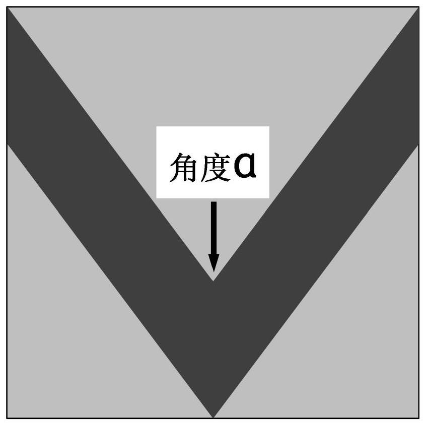
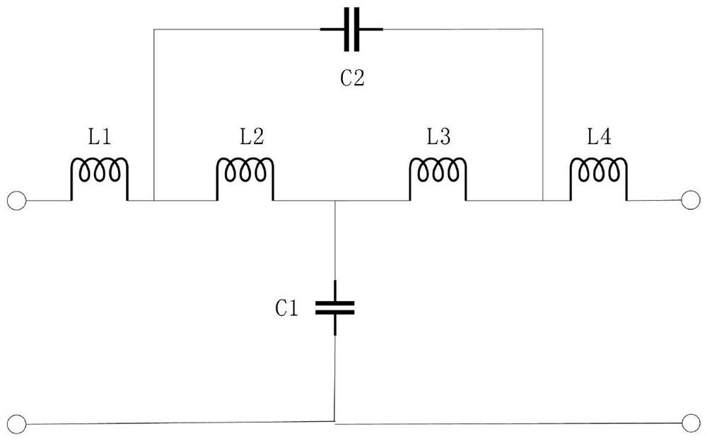
[0068] Embodiment 1: A directional coupler made of a bent line such as Figure 4-5 As shown, a bent line structure is used in the coupling area. Compared with parallel coupled lines, a single bent line can generate higher capacitance. At the same time, the coupling between two bent lines is due to the bending. When the overall size is reduced, the coupling area of ​​the two coupling lines can also be increased to generate more capacitance, so that the coupler can cover a wider frequency band. When making a directional coupler, you will know the size of the capacitance The center frequency can be changed, and we can also adjust the bending angle ɑ of the bend line to achieve fine-tuning of the center frequency, which makes it easier and more convenient for us to optimize the model.

[0069] The broadband directional coupler design based on the meander line equivalent circuit is characterized by Rogers4350 dielectric substrate SUB, the dielectric constant of the dielectric subst...


PUM


Abstract

The invention discloses a broadband directional coupler based on a bent line structure equivalent circuit. The broadband directional coupler is composed of a metal grounding plate, a dielectric substrate and a bent coupling line part coupled to the upper surface of the dielectric substrate. The metal grounding plate is arranged on the lower surface of the dielectric substrate; the bending type coupling line part comprises an input port P1, an output port P2, a coupling port P3, an isolation port P4, a first bending type coupling line B1 and a second bending type coupling line B2; the first bent coupling line B1 is connected with the input port P1 and the output port P2 respectively; the second bending type coupling line B2 is connected with the coupling port P3 and the isolation port P4. The parallel coupling lines are bent, parallel capacitance C2 is generated under the bending condition, the size of the parallel capacitance C2 is controlled through the bending angle alpha, meanwhile, additional parallel capacitance is generated, inductance can be counteracted to a certain degree, and therefore better impedance matching is achieved.

Description

technical field [0001] The invention relates to the technical field of directional coupler design, in particular to a broadband directional coupler based on an equivalent circuit of a meander line structure. Background technique [0002] As an important microwave / millimeter wave component in modern communication systems, the directional coupler's essential function is to distribute the power of signals within a certain frequency range according to a certain ratio, and it can also be used for power synthesis. It is generally used for sampling and monitoring of signals, and also has the function of isolation. The performance of directional couplers is mainly measured by indicators such as operating frequency band, directivity, standing wave ratio, coupling degree, and insertion loss. [0003] After decades of research and exploration by experts and scholars in the industry, the comprehensive method and related design diagrams of directional couplers have been relatively matur...

Claims


Application Information

Patent Timeline
Patent Type & Authority Applications(China)
IPC IPC(8): H01P5/18
CPCH01P5/184
Inventor 丁大维凌少旭杨利霞黄志祥
Owner ANHUI UNIVERSITY
Learn More