Multifunctional surface cleaning machine with good exhaust effect

A multi-functional, cleaning machine technology, applied to cleaning equipment, exhaust diffuser, vacuum cleaners, etc., can solve problems such as abnormal work, affecting the electrical connection of suction source components, vibration of suction source components, etc., to improve efficiency and reduce The danger of people blowing, the effect of smooth transmission

Active Publication Date: 2022-05-06
SHARKNINJA CHINA TECH CO LTD
View PDF7 Cites 0 Cited by
  • Summary
  • Abstract
  • Description
  • Claims
  • Application Information

AI Technical Summary

Problems solved by technology

When the power source component is installed on the body, if the exhaust air is not smooth, it will easily cause the vibration of the suction source component, which will seriously affect the electrical connection between the suction source component and the body, resulting in abnormal operation

Method used


Image

  • Multifunctional surface cleaning machine with good exhaust effect
  • Multifunctional surface cleaning machine with good exhaust effect
  • Multifunctional surface cleaning machine with good exhaust effect

Examples


Embodiment 1

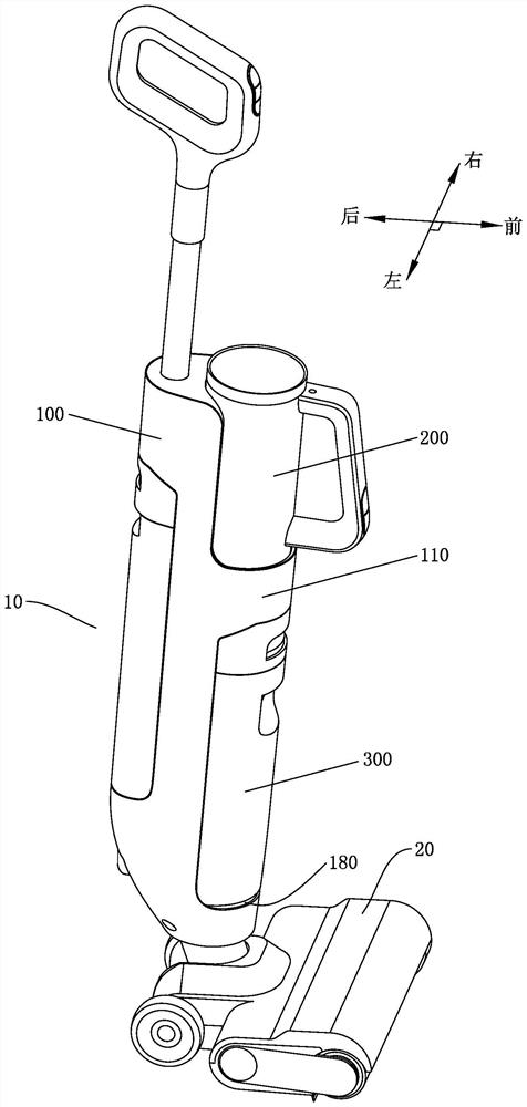
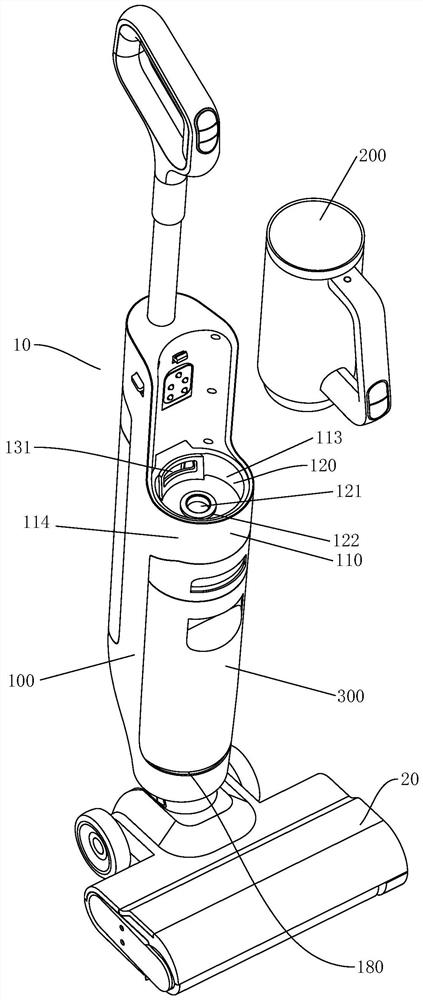
[0047] As an embodiment of the multifunctional surface cleaning machine of the present invention, as Figure 1 to Figure 9As shown, it includes a fuselage 10 with a positioning part 110 and a ground brush 20 pivotally connected to the bottom of the fuselage 10. The positioning part 110 protrudes outward from the fuselage 10. The upper and lower suction source assembly 200 and the dirt bucket 300 . The suction source assembly 200 is provided with an air inlet 210 and an air outlet 220, and the positioning part 110 is provided with a wind direction conversion chamber 120, and the center of the bottom wall of the wind direction conversion chamber 120 is provided with a vent 121 communicating with the dirt bucket 300, An isolating ring 122 is arranged around the vent 121 to isolate the wind direction conversion chamber 120 from the vent 121, and a sound-insulating gasket 150 is arranged inside the isolating ring, and the positioning part 110 includes a circular inner shell 113 and...

Embodiment 2

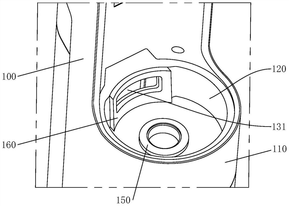
[0075] As an embodiment of the multifunctional surface cleaning machine of the present invention, as Figure 10 to Figure 12 As shown, the air exhaust cavity 130 is arranged in the positioning portion 110 and extends downward, the inlet 131 of the exhaust cavity 130 is arranged in the air direction conversion cavity 120, the inlet 131 of the exhaust cavity 130 is arranged around the vent 121, and the The inlet 131 of the exhaust chamber 130 is fan-shaped, and the outlet 132 of the exhaust chamber 130 is arranged near the fuselage 10. The projection of the outlet 132 in the horizontal plane does not fall in the inlet 131, and the outlet 132 of the exhaust chamber 130 Located on the bottom side of the positioning part 110, such a structure makes the inlet 131 and outlet 132 of the exhaust chamber not facing each other, ensuring that the wind will not be discharged directly, but enters the exhaust air through the inlet 131 of the exhaust chamber 130 In the cavity 130, the exhaust...

Embodiment 3

[0083]combine Figure 13 The difference between the present embodiment and the first embodiment is that: an air inlet 210 and an air outlet 220 are respectively provided on the front surface of the suction source assembly 200 . Specifically, the air inlet 210 and the air outlet 220 are arranged at different heights on the end surface. Preferably, the air outlet 220 is arranged around the air inlet 210, at Figure 13 , the air outlet 220 is higher than the air inlet 210 .

[0084] In order to make the air inlet passage 111 and the air inlet 210 can seal butt fit, the bottom wall of the wind direction conversion chamber 120 is provided with a sealing ring 150 located on the outer periphery of the top end of the air inlet passage 111 . The positioning part is provided with a buffer cavity, the air outlet of the suction source assembly is connected to one end of the buffer cavity in the wind direction conversion cavity, the buffer cavity is hidden inside the positioning part, an...


PUM


Abstract

The multifunctional surface cleaning machine comprises a machine body with a positioning part and a ground brush, the positioning part protrudes outwards from the machine body, the machine body is provided with a suction source assembly and a dirt containing barrel which are detachably arranged on the upper portion and the lower portion of the positioning part respectively, the suction source assembly is provided with an air inlet and an air outlet, and the positioning part is provided with an air direction conversion cavity. The bottom wall of the air direction conversion cavity is provided with an air vent communicated with the sewage containing barrel, the periphery of the air vent is provided with an isolating ring used for isolating the air direction conversion cavity from the air vent, and sewage suction airflow flowing through the sewage containing barrel flows through the suction source assembly, is turned through the air direction conversion cavity and then is discharged through the interior of the machine body. Due to the existence of the isolating ring and the wind direction conversion cavity, the flowing continuity and smoothness of the sewage suction airflow between the suction source assembly and the machine body are ensured, the noise generated by air leakage is avoided, the noise of the sewage suction airflow is further reduced, and the use experience of a user is improved.

Description

technical field [0001] The invention relates to the field of cleaning appliances, in particular to a multifunctional surface cleaning machine. Background technique [0002] With the wide application of electrical equipment and the gradual improvement of the automation process, more and more electric cleaning devices are gradually accepted by people, such as sweeping robots, vacuum cleaners and floor washing machines. Most of the existing scrubbers have suction source components fixed on the fuselage, thus ensuring that the wind sucked up by the suction source components can be attenuated after passing through the fuselage, reducing noise and ensuring the safety of customers . [0003] Later, in order to achieve multi-function, a wet and dry cleaning machine appeared in the market. The specific solution is to detachably set the suction source assembly on the body, and set a water tank and a sewage bucket on the body to clean the dirt on the ground. Stubborn stains; and the ...

Claims


Application Information

Patent Timeline
IPC IPC(8): A47L5/22A47L9/00A47L9/10
CPCA47L9/00A47L9/0081A47L11/302A47L11/40A47L11/4013A47L11/4016A47L11/4097
Inventor 朱泽春王丽军朱广
Owner SHARKNINJA CHINA TECH CO LTD
Why Eureka
Try Eureka