Device and method for electric bicycle sliding and braking energy recharging system

A technology for electric bicycles and braking energy, applied in electric braking systems, electric vehicles, bicycle accessories, etc., to achieve the effects of improving battery life, reducing waste, and being suitable for popularization and use

Active Publication Date: 2022-05-06
WUXI JIETONG AUTOCYCLE
View PDF12 Cites 0 Cited by
  • Summary
  • Abstract
  • Description
  • Claims
  • Application Information

AI Technical Summary

Problems solved by technology

[0004] However, the above-mentioned vehicle energy recovery device has the following technical defects in use: because it adopts the internal gear on the energy recovery block to drive the central gear to rotate at a high speed through the planetary gear to drive the generator to generate electricity to realize energy recovery when the vehicle brakes, that is, the vehicle The energy recovery device uses the central gear to drive the generator to rotate during the energy recovery, and the energy recovery is completed under the braking state. For the electric bicycle, its operating state includes not only acceleration and braking, but also coasting. state, and there is a certain difference in the energy recovery of the electric bicycle when it is coasting or braking, that is, when the electric bicycle is in the coasting state, its power generation structure should control the resistance to the wheels during power generation within a small range to ensure The normal sliding of the wheels; when the electric bicycle is in the braking state, its power generation structure should be able to exert a certain resistance effect on the running of the wheels when generating electricity, so as to be able to play the effect of auxiliary braking. Therefore, the present invention proposes a Device for electric bicycle coasting and braking energy recovery system for judging energy recovery mode

Method used


Image

  • Device and method for electric bicycle sliding and braking energy recharging system
  • Device and method for electric bicycle sliding and braking energy recharging system
  • Device and method for electric bicycle sliding and braking energy recharging system

Examples


Embodiment Construction

[0063] In order to make the technical means, creative features, goals and effects achieved by the present invention easy to understand, the following drawings and in conjunction with specific implementation methods further illustrate the present invention.

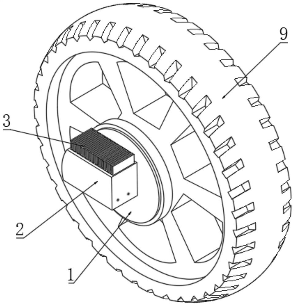
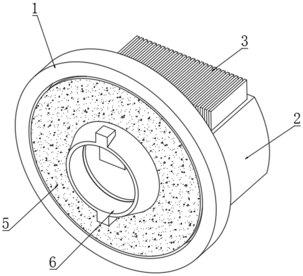
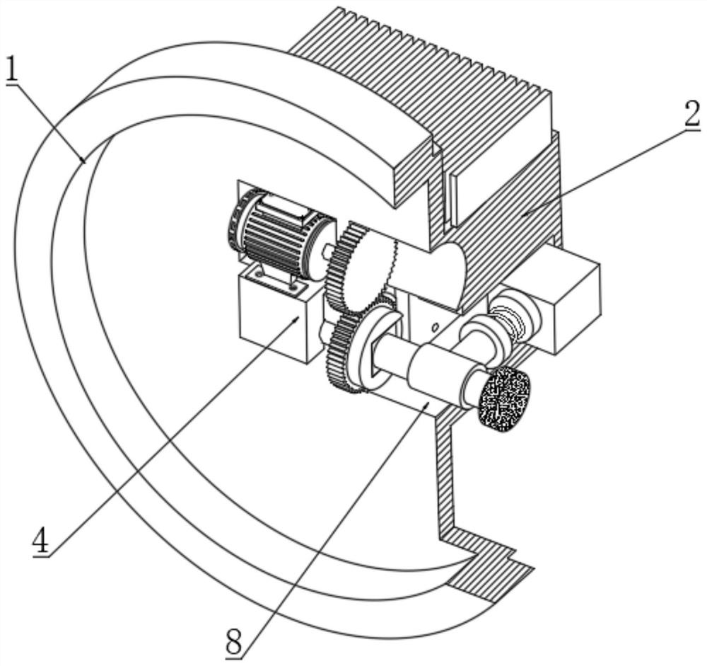
[0064] Such as Figure 1-Figure 5 As shown, a device and method for an electric bicycle sliding and braking energy recovery system, including an electric bicycle front wheel 9, an electric control switch 10, a main control chip 11, a current sensor 7 and a speed sensor 12, and an electric bicycle front wheel 9 One side of the outer cover 1 is provided with an outer cover 1, and the side of the outer cover 1 away from the front wheel 9 of the electric bicycle is provided with a housing 2, and the outer cover 1 is fixedly connected and integrally formed; the electric control switch 10 and the main control chip 11 are arranged on the electric bicycle. handle, and the main control chip 11 is electrically connected with the cur...


PUM


Abstract

The invention discloses a device and method for an electric bicycle sliding and braking energy recharging system, and particularly relates to the technical field related to electric bicycles. The device comprises an outer cover, a shell, a main control chip, an electric control switch, a current sensor and a speed sensor; a connecting part is fixedly mounted on the side, close to the front wheel of the electric bicycle, of the grinding wheel, a mounting cavity is formed in the inner wall of the outer cover, and an energy recovery system is arranged in the mounting cavity. By arranging the electric control switch, the main control chip, the current sensor, the speed sensor and the energy recovery system, when the electric bicycle is in a sliding state or a braking state, the micro generator can work, then energy recovery is achieved, the endurance of the electric bicycle can be effectively improved, energy is saved, the structure is simple, the manufacturing difficulty is low, and the cost is low. The method is suitable for popularization.

Description

technical field [0001] The invention relates to the technical field related to electric bicycles, in particular to a device and method for an electric bicycle sliding and braking energy recovery system. Background technique [0002] Electric bicycles, that is, electric-driven bicycles, electric bicycles use batteries as energy sources, through controllers, motors and other components, convert electrical energy into mechanical energy movement, to control the current and change the speed of the vehicle. Electric bicycles often brake during driving. If the number of brakes is too high, electric energy will be wasted. Therefore, it will have a negative impact on the battery life of electric bicycles. Compensation devices have been widely used. [0003] Patent No. CN201210369168.0 discloses a vehicle brake energy recovery device, including a base, an energy recovery mechanism, a power generation mechanism, a locking mechanism and a control system. The energy recovery mechanism i...

Claims


Application Information

Patent Timeline
Patent Type & Authority Applications(China)
IPC IPC(8): B60L7/10B60L7/18B62J45/412B62J45/423B62J45/41
CPCB60L7/10B60L7/18B62J45/412B62J45/423B62J45/41B60L2200/46B60L2260/40
Inventor 张宸源
Owner WUXI JIETONG AUTOCYCLE
Why Eureka
Try Eureka