Eureka AIR delivers breakthrough ideas for toughest innovation challenges, trusted by R&D personnel around the world.

Ex-pile detector calibration method, computer equipment and storage medium

A detector and core technology, applied in the field of nuclear power, can solve the problems of increasing the operation and maintenance cost of the detector system in the reactor, occupying the critical path of unit power increase, and increasing the risk of probe jamming, etc., so as to reduce the boride dilution operation , Reduce the generation of radioactive waste liquid, reduce the effect of the risk of probe jamming

Pending Publication Date: 2022-05-06
CHINA NUCLEAR POWER TECH RES INST CO LTD +3
View PDF0 Cites 0 Cited by
  • Summary
  • Abstract
  • Description
  • Claims
  • Application Information

AI Technical Summary

Problems solved by technology

If the intervention is not timely, the ΔI oscillation will diverge, and there is a risk of triggering the core protection signal
Especially at the end of life, ΔI is more difficult to control and the risk is higher
[0007] (2) The frequent use of the in-core monitoring system in the test increases the risk of probe jamming and accelerates the aging of the detector, which increases the operation and maintenance cost of the in-core detector system
[0008] (3) The test lasted about 8-10 hours, requiring continuous operation of on-site personnel and backup support personnel, which is prone to human risk
[0009] (4) Boronation dilution operation is required during the test, which increases the generation of radioactive waste liquid
[0010] (5) Starting each power platform to perform the test after refueling will occupy the critical path of unit power increase, resulting in loss of power generation

Method used


Image

  • Ex-pile detector calibration method, computer equipment and storage medium
  • Ex-pile detector calibration method, computer equipment and storage medium
  • Ex-pile detector calibration method, computer equipment and storage medium

Examples


Embodiment Construction

[0052] In order to have a clearer understanding of the technical features, purposes and effects of the present invention, the specific implementation manners of the present invention will now be described in detail with reference to the accompanying drawings. In the following description, it should be understood that "front", "rear", "upper", "lower", "left", "right", "longitudinal", "horizontal", "vertical", "horizontal", The orientation or positional relationship indicated by "top", "bottom", "inner", "outer", "head", "tail", etc. is based on the orientation or positional relationship shown in the drawings, and is constructed and operated in a specific orientation, It is only for the convenience of describing the technical solution, but does not indicate that the referred device or element must have a specific orientation, so it should not be construed as a limitation of the present invention.

[0053] It should also be noted that terms such as "installation", "connection", ...


PUM


Abstract

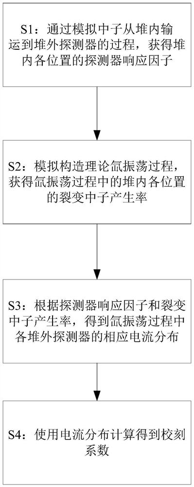
The invention relates to an out-of-pile detector calibration method, which comprises the following steps of: S1, acquiring detector response factors at all positions in a pile by simulating a process of transporting neutrons from the inside of the pile to an out-of-pile detector; s2, a theoretical xenon oscillation process is simulated and constructed, and fission neutron generation rates of all positions in the reactor in the xenon oscillation process are obtained; s3, according to the detector response factors and the fission neutron generation rate, response current distribution of all the out-of-pile detectors in the xenon oscillation process is obtained; and S4, calculating the calibration coefficient by using the current distribution. According to the invention, while the implementation of a field xenon oscillation test is cancelled, a set of complete calibration coefficient with enough precision can still be provided, the disturbance to a reactor core is reduced, and the control difficulty of the reactor (especially at the end of the service life) is reduced, so that the pressure of operators is also reduced.

Description

technical field [0001] The present invention relates to the technical field of nuclear power, in particular to an out-of-core detector calibration method, computer equipment and a storage medium. Background technique [0002] In the field of nuclear power, the fuel assembly is the core component and also the component with the highest concentration of radioactive substances. Fuel assemblies are usually arranged in closed pressure vessels to form the core. In order to monitor the working status of the core, an external nuclear radiation detection system is usually configured, so that the operation process of the core can be monitored. Among them, it is mainly monitored (nuclear power, ΔI, TILT, LOCA margin) and protected (OPDT, OTDT, etc.) by the power range detector set outside the core. [0003] In order to confirm the normal realization of the function of the extracore detector, it is necessary to update its calibration coefficient regularly during the operation of the c...

Claims


Application Information

Patent Timeline
Patent Type & Authority Applications(China)
IPC IPC(8): G21C17/10G21C17/108G06F30/25
CPCG21C17/10G21C17/108G06F30/25Y02E30/30
Inventor 李贵杰李一鸣于超林俊王鑫薛慧智别业旺李志军韩嵩朱宇翔
Owner CHINA NUCLEAR POWER TECH RES INST CO LTD
Why Eureka
Eureka Blog
Learn More